Hydraulic piling machine pile controller

A hydraulic and hydraulic cylinder technology, applied in the field of control devices for prefabricated piles, can solve problems such as changes in the level of the working platform, affecting construction efficiency and safety, and affecting the construction quality of foundation piles, and achieves high orientation, simple structure, and transmission. Stable and reliable structure

Inactive Publication Date: 2014-08-06
ZHONGBEI UNIV
View PDF5 Cites 11 Cited by
  • Summary
  • Abstract
  • Description
  • Claims
  • Application Information

AI Technical Summary

Problems solved by technology

However, as the construction progresses, the levelness of the working platform will change, and at the same time, the coaxiality between the piles and the piles will affect the construction quality of the foundation piles.
[0005] At present, in the process of implanting foundation piles of all hydraulic pile drivers, the positioning of the first prefabricated pile is carried out by the staff's visual inspection and mobile equipment, and it is carried out during the lifting of the prefabricated pile, which will inevitably affect the construction. efficiency and safety
In addition, the connection between piles is also carried out during the lifting process of prefabricated piles, relying on manual centering and connection will also affect construction efficiency and safety

Method used


Image

  • Hydraulic piling machine pile controller
  • Hydraulic piling machine pile controller
  • Hydraulic piling machine pile controller

Examples


Embodiment Construction

[0024] In order to make the technical means, creative features, goals and effects achieved by the present invention easy to understand, the technical solutions in the embodiments of the present invention will be clearly and completely described below in conjunction with the accompanying drawings in the embodiments of the present invention.

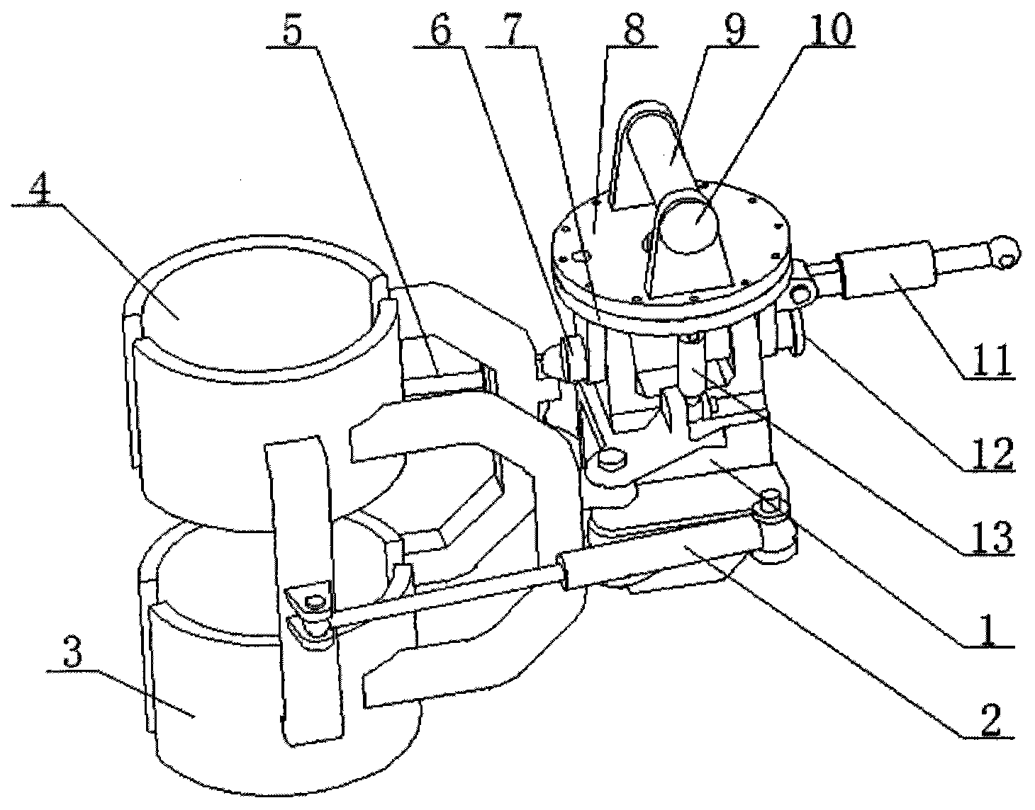
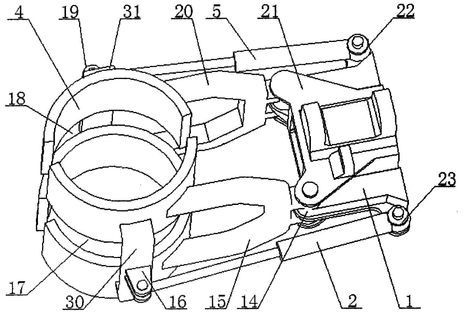
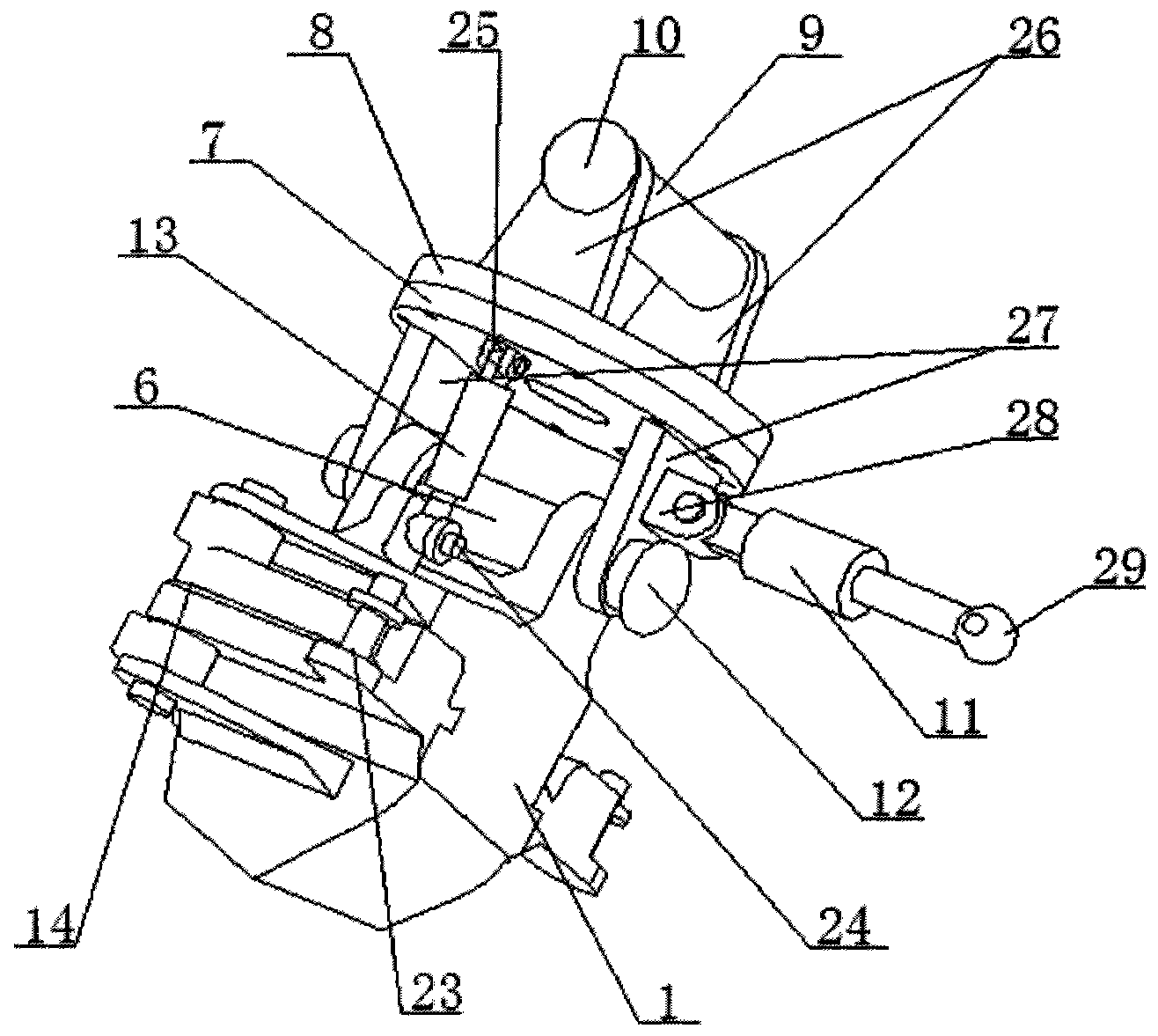
[0025] see Figure 1-5 , the specific embodiment is realized by adopting the following technical scheme, which includes a pile controller box and a pile controller vertical adjustment mechanism connected thereto, and the pile controller box includes a control box 1, and the control box 1 is provided with a left swing arm hinged ear 21 and a right swing arm hinged ear 14 as mirror images on both sides of 1, the clamping mechanism installed on the left swing arm hinged ear 21 and the right swing arm hinged ear 14, the pile control device adjusting The vertical mechanism includes a lower flange 7 that rotates with the control box 1. The lower...


PUM


Abstract

The invention discloses a hydraulic piling machine pile controller which comprises a pile controller box body and a pile controller verticality adjusting mechanism connected with the pile controller box body. The pile controller box body comprises a control box body. A left swing arm hinge lug and a right swing arm hinge lug are arranged on the two sides of the control box body in a mirror-image mode. Clamping mechanisms are arranged on the left swing arm hinge lug and the right swing arm hinge lug. The pile controller verticality adjusting mechanism comprises a lower flange disc matched with the control box body in a rotating mode. The lower flange disc is connected with an upper flange disc through a periphery-arranged bolt. A longitudinal-shaft-surrounding verticality adjusting hydraulic cylinder is arranged on one side of the lower flange disc. One end of the longitudinal-shaft-surrounding verticality adjusting hydraulic cylinder is connected with a first longitudinal-shaft-surrounding verticality adjusting hydraulic cylinder hinge lug fixed at the bottom of the lower flange disc. The hydraulic piling machine pile controller is simple in structure, a left swing arm and a right swing arm are used for clamping and guiding a precast pile, the whole transmission structure stability and reliability are guaranteed, guiding performance is high, when a first pile is implanted, clamping locating is carried out through the pile controller, a guiding function is achieved during a precast pile implanting process, when a following pile is implanted, clamping of the ends of the two precast piles can be carried out through the pile controller, and coaxial connecting between the piles is carried out.

Description

technical field [0001] The invention belongs to the technical field of pile drivers for construction, and in particular relates to a control device for prefabricated piles in the working process of hydraulic pile drivers. Background technique [0002] In the early 1950s, all the foundation construction in our country used old-fashioned steam pile drivers and heavy drop hammers imported from abroad. During the first five-year period, the country began to imitate foreign 3-10 tons single-acting and double-acting steam pile drivers. The 1950s was the budding period of my country's pile machinery industry. In the early 1960s, the pile machinery manufacturing industry and professional research room began to be established. From then on, the development period of my country's self-developed pile machinery began. By the 1970s, my country had successfully developed and mass-produced barrel-type diesel piling hammers, track-type three-point piling frames, sinking and pulling pile h...

Claims


Application Information

Patent Timeline
Patent Type & Authority Applications(China)
IPC IPC(8): E02D13/04
Inventor 马富康董小瑞王锋田淑华郭顺宏
Owner ZHONGBEI UNIV
Why Eureka
Try Eureka