Film-cooled turbine blade for fluid machinery

A technology of turbine blades and fluid machinery, applied in the direction of mechanical equipment, blade support components, engine components, etc.

Inactive Publication Date: 2014-08-06
SIEMENS AG
View PDF5 Cites 5 Cited by
  • Summary
  • Abstract
  • Description
  • Claims
  • Application Information

AI Technical Summary

Problems solved by technology

For this purpose, suitable materials and combinations of materials are available for the turbine blades, however, according to the current state of the art, the potential of these materials or combinations of materials for increasing the thermal efficiency of gas turbines has not been fully exploited

Method used


Image

  • Film-cooled turbine blade for fluid machinery
  • Film-cooled turbine blade for fluid machinery
  • Film-cooled turbine blade for fluid machinery

Examples


Embodiment Construction

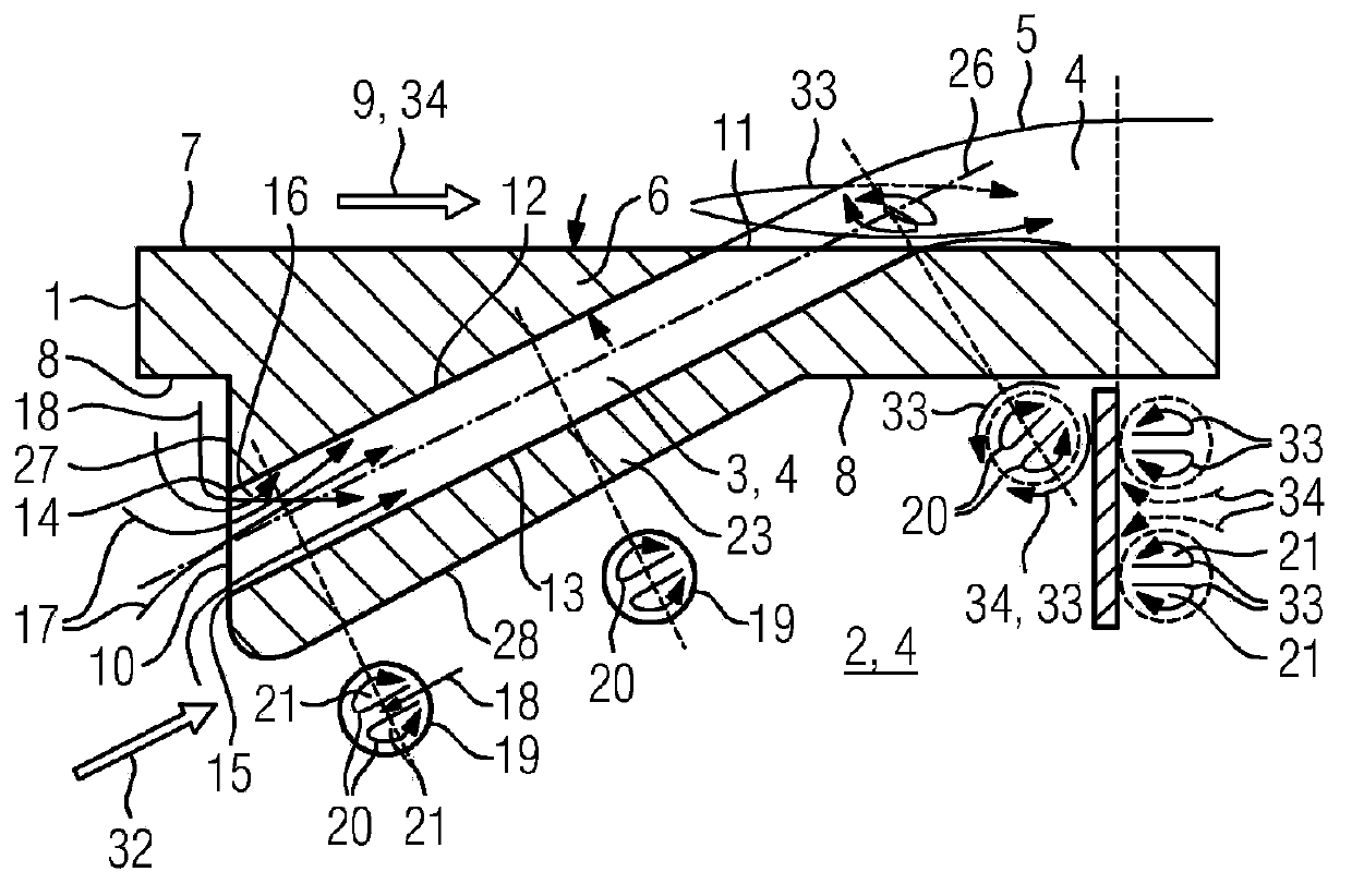
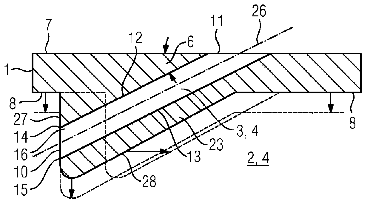
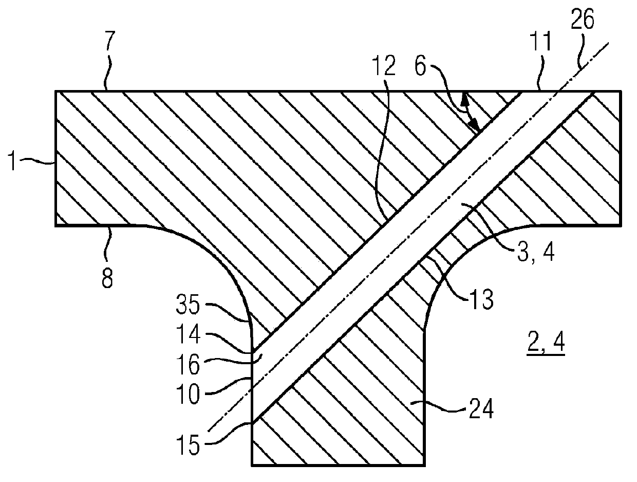
[0020] Figures 1 to 6 A sectional view of the outer wall 1 of a turbine blade of a fluid machine is shown. The outer wall 1 delimits the inner cavity 2 and has an outer side 7 and an inner side 8 . During hydromechanical operation, a hot gas flow 34 occurs on the outer side 7 with a hot gas main flow direction 9 parallel to the outer side 7 , which is directed towards the trailing edge (not shown in the figure) of the turbine blade. A continuous channel 3 with a circular cross section 19 is introduced into the outer wall 1 , which is inclined in the through-flow direction directed from the inside to the outside relative to the trailing edge of the turbine blade and encloses a sharp angle of inclination 6 with the outer side 7 .

[0021] Figures 1 to 6 The continuous channel 3 in has an inlet 10 on the inside and an outlet 11 on the outside. Furthermore, the continuous channel 3 has an axis 26 , an upstream side 12 and a downstream side 13 . The inlet 10 of the continuou...


PUM


Abstract

A turbine blade for fluid machinery is provided with an outer wall, wherein an inner cavity of the turbine blade is limitedby the outer wall; a cooling fluid used for performing film cooling of the turbine blade can be supplied in the inner cavity; one or more continuous channels are formedin the outer wall; the cooling fluid can penetrate through one or more continuous channels from the inner cavity, flows towards the exterior of the turbine blade, and is used for forming a cooling film on the outer side of the outer wall, and the one or more continuous channelsare inclined towards the rear edge of the turbine blade; relative to other edge sections of inlets, the edge sections at the inlets of the continuous channels and on the sides located atthe upstream of the continuous channels are sharp ridge-shaped, as a result, partition areas can be formed in the continuous channelsforthe flow of the cooling fluid, and transverse flow inthe center of the cooling fluid is generated via the parathion areas; the transverse flow points to the sides of the continuous channels, opposite to the partition areas. Therefore, a pair of reversededdy currentsis formed in the continuous channels, and the speed vector of the flow of thecooling fluid between the centers of the eddy currentspoints to the sides of the continuous channels, located at the downstream.

Description

technical field [0001] The invention relates to a turbine blade for a fluid machine, wherein the turbine blade is film cooled. Background technique [0002] Fluid machines, in particular gas turbines, have a turbine in which hot gas, previously compressed in a compressor and heated in a combustion chamber, is expanded to obtain work. For a high mass flow of the hot gas and thus for a high performance range of the gas turbine, the turbine is designed in an axial design, the turbine being formed by a plurality of blade rings arranged one behind the other in the flow direction. The blade ring has rotor blades and guide vanes arranged on the circumference, wherein the rotor blades are attached to the rotor of the gas turbine and the guide vanes are attached to the housing of the gas turbine. [0003] The higher the inlet temperature of the hot gas entering the turbine, the higher the thermodynamic efficiency of the gas turbine. Conversely, limits are set with regard to the hea...

Claims


Application Information

Patent Timeline
IPC IPC(8): F01D5/18F01D9/02
Inventor 安德烈亚斯·黑泽尔豪斯
Owner SIEMENS AG
Why Eureka
Try Eureka