Pumping unit with liquid storage tank and sliding tapered bearings

A pumping device and a tapered bearing technology, applied in the field of pumping devices for automatically removing flocs

Inactive Publication Date: 2016-03-23
缪海靖 +1
View PDF5 Cites 0 Cited by
  • Summary
  • Abstract
  • Description
  • Claims
  • Application Information

AI Technical Summary

Problems solved by technology

Because the existing pumping devices often have requirements for water quality, and the pumping devices used in the occasions with more impurities will be regularly removed from the pumping water source for cleaning, so this problem can still be tolerated

Method used


Image

  • Pumping unit with liquid storage tank and sliding tapered bearings
  • Pumping unit with liquid storage tank and sliding tapered bearings
  • Pumping unit with liquid storage tank and sliding tapered bearings

Examples


Embodiment Construction

[0020] Attached below Figure 1-4 , the present invention will be described in detail.

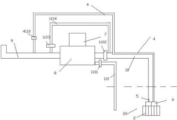
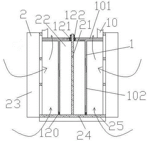
[0021] A pumping device with a liquid storage tank and a sliding tapered bearing, comprising a power unit 7, a pumping device body 8, a water outlet pipe 9, a water inlet pipe 10 and an inlet water filter device 20, wherein the power unit 7 is used for pumping water The device body 8 provides power, and the water pumping device body 8 can generate pressurized water flow and send it out through the water outlet pipe 9, and the water inlet pipe 10 is used to draw water flow from a water source.

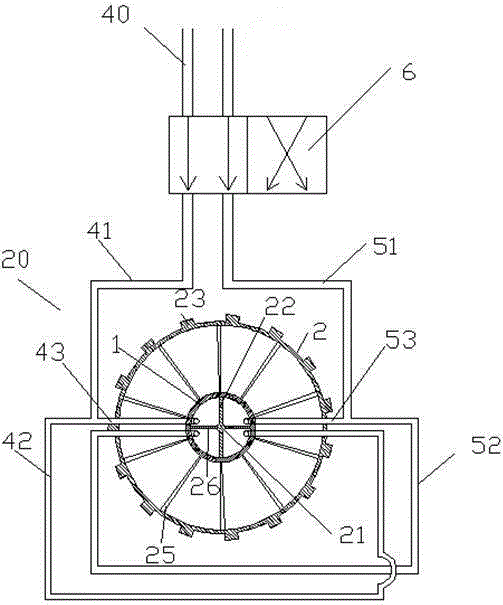
[0022] The pumping device also includes a pressure return pipe 4, the first end of the pressure return pipe 4 is in fluid communication with the outlet pipe 9, and the pressure return pipe 4 extends from the first end to bypass the power unit 7 and The pumping device body 8 enters the water inlet pipe 10 and continues to extend to the second end 40 in the water inlet pipe 10 .

[0023] The water i...


PUM


Abstract

A water pumping device with a liquid storage tank and a sliding conical bearing comprises a power device (7), a water pumping device body (8), a water outlet pipe (9), a water inlet pipe (10) and an inflowing water filtering device (20). The power device (7) is used for providing power for the water pumping device body (8), the water pumping device body (8) can generate pressurized water and send out the water through the water outlet pipe (9), and the water inlet pipe (10) is used for drawing the water from a water source.

Description

technical field [0001] The invention relates to a water pumping device, more particularly to a water pumping device capable of automatically removing flocs. Background technique [0002] A pumping device is a water-drawing device widely used in agriculture, green space maintenance, and industry. Because the operating environment of the pumping device is different, the water quality is different. Therefore, in order to prevent the normal operation of the pumping device from being affected by impurities in the water, a filter structure is often provided at the end of the water inlet pipe of the pumping device. [0003] However, due to the strong suction formed by the pumping device during operation, it is easy to absorb a large amount of impurities in the vicinity of the end of the water inlet pipe; and some floc impurities stay at the filter structure at the end of the water inlet pipe; over time, these flocculent The accumulation of impurities will affect the water inlet pe...

Claims


Application Information

Patent Timeline
Patent Type & Authority Patents(China)
IPC IPC(8): F04B53/20F04B53/00F04B49/22
Inventor 何丽进
Owner 缪海靖
Why Eureka
Try Eureka