Anode-cathode connector and connector device for battery or capacitor

A technology of connectors and positive and negative poles, which is applied in the field of electronic component testing, can solve the problems of inaccurate battery or capacitor results, damage to the positive and negative poles of batteries or capacitors, and achieve the effects of ensuring product quality, preventing damage, and avoiding damage

Inactive Publication Date: 2014-08-06
REPOWER TECH CO LTD
View PDF9 Cites 3 Cited by
  • Summary
  • Abstract
  • Description
  • Claims
  • Application Information

AI Technical Summary

Problems solved by technology

[0004] The purpose of the present invention is to provide a battery or capacitor positive and negative connectors and a connector device, aiming to solve the problem of inaccurate battery or capacitor detection results in the prior art, or even damage to the positive and negative electrodes of the battery or capacitor

Method used


Image

  • Anode-cathode connector and connector device for battery or capacitor
  • Anode-cathode connector and connector device for battery or capacitor
  • Anode-cathode connector and connector device for battery or capacitor

Examples


Embodiment 1

[0041] Such as Figure 1-8 Shown is a preferred embodiment provided by the present invention.

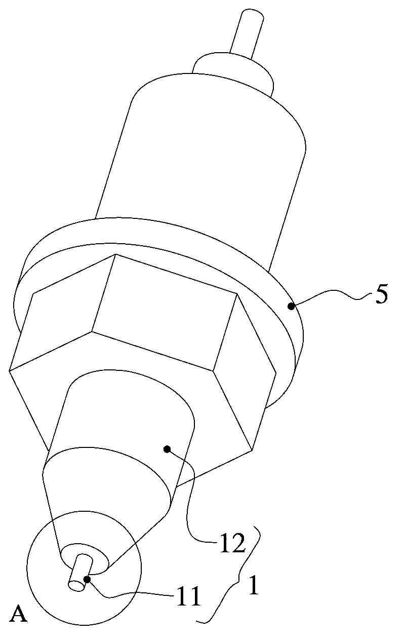
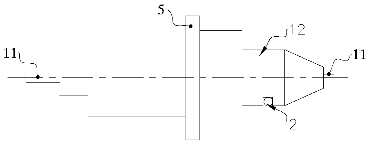
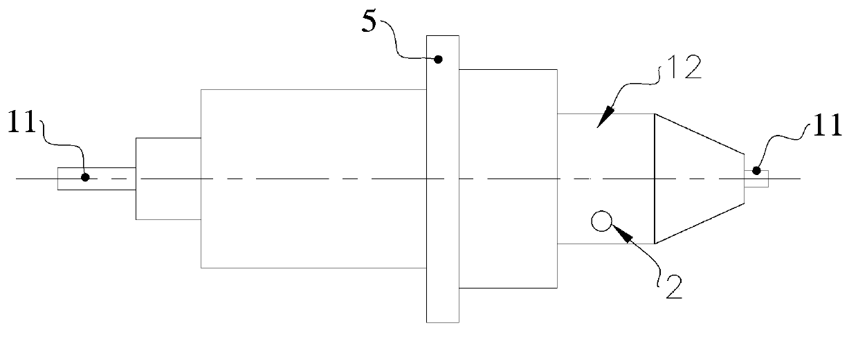
[0042] The present invention is achieved in this way, a connecting piece 1 for the positive and negative poles of a battery or capacitor, the connecting piece 1 has a metal part for conduction detection of the positive and negative poles of the battery or capacitor, and the metal part is provided with a connecting piece for detecting Heat sensor 2 for heating temperature. The thermal sensor 2 has high sensitivity. By setting the thermal sensor 2 on the connector 1, when testing the battery or capacitor 100, the temperature on the connector 1 of the positive and negative poles of the battery or capacitor can be monitored in real time. Calorific value, when the calorific value of the positive and negative connectors 1 of the battery or capacitor exceeds the safe value, the test equipment will cut off the voltage loop and current loop of the test battery or capacitor, and the device w...

Embodiment 2

[0058] The difference between this embodiment and the first embodiment is that the thermal sensor 2 and the connecting piece 1 are arranged separately. Such as Figure 12 As shown, one end of the connector 1 is connected with a connection wire 13 for connecting to an external testing device, and the thermal sensor 2 is sandwiched on the connector 1 by a fastener 14 . In this way, when testing a battery or a capacitor, the heat generated by the connection of the thermal sensor 2 can be detected, thereby avoiding damage to the battery or capacitor due to overheating.

Embodiment 3

[0060] Such as Figure 13 with Figure 14 As shown, the connector 1 in this embodiment includes a first connector 11 and a second connector 12 hinged to each other, and a first elastic member is sandwiched between the first connector 11 and the second connector 12 3. In this embodiment, the first elastic member 3 is a torsion spring. The thermal sensor 2 is pasted or embedded or fused on the metal part of the second connecting member 12 .

[0061] In this way, the positive and negative poles of the battery or capacitor 100 are clamped by the first connecting piece 11 and the second connecting piece 12, and while the electrical signal in the battery or capacitor 100 is turned on, the electrical signal on the connecting piece 1 is detected. The heat keeps the battery or capacitor 100 in a good testing environment all the time, ensuring the stability and accuracy of testing.


PUM


Abstract

The invention belongs to the technical field of electronic component test, and particularly relates to an anode-cathode connector and a connector device for a battery or a capacitor. The connector comprises a metal portion for on detection of an anode and a cathode of the battery or the capacitor, the metal portion is provided with a heat sensor used for detecting heating temperature of the connector, and the heat sensor is embedded, integrated or attached onto the connector. The connector device comprises a fixed frame and a moving frame spaced from the fixed frame, and the battery or capacitor anode-cathode connectors matched mutually are disposed on the fixed frame and the moving frame respectively. By the aid of the heat sensor arranged on the connector, when the battery or the capacitor is tested by test equipment, heat value on the connector can be monitored constantly, and accordingly the connector can be avoided from transferring heat to the battery or the capacitor to affect test precision; moreover, the battery or the capacitor can be protected from damage due to overheating, and product quality of the battery or the capacitor is guaranteed.

Description

technical field [0001] The invention belongs to the technical field of electronic component testing, and in particular relates to a positive and negative connector of a battery or capacitor and a connector device. Background technique [0002] At present, there are various connectors on the market for testing the positive and negative electrodes of the battery or capacitor. When the battery is charging and discharging, the contact resistance is likely to occur at the part where the connector contacts the positive and negative electrodes of the battery or capacitor. The contact resistance is determined by the shrinkage resistance ( The resistance of the current line due to the incomplete contraction of the contact area) and the film layer resistance (adhesive film, oxide film, polluted film, etc. on the surface of the test electrode or the positive and negative electrodes of the battery or capacitor). Contact resistance, like friction, always exists in the part where the test...

Claims


Application Information

Patent Timeline
IPC IPC(8): G01R1/04
Inventor 毛广甫
Owner REPOWER TECH CO LTD
Why Eureka
Try Eureka