
Self-adaptive acoustic imaging method

An imaging method and self-adaptive technology, applied in the direction of sound wave re-radiation, using re-radiation, measuring devices, etc., can solve the problem of increasing side lobe levels in non-target areas

Inactive Publication Date: 2014-08-06
INST OF ACOUSTICS CHINESE ACAD OF SCI
View PDF3 Cites 12 Cited by
  • Summary
  • Abstract
  • Description
  • Claims
  • Application Information

AI Technical Summary

Problems solved by technology

Incoherent stacking can lead to increased sidelobe levels in some untargeted regions

Method used


Image

  • Self-adaptive acoustic imaging method
  • Self-adaptive acoustic imaging method
  • Self-adaptive acoustic imaging method

Examples


Embodiment Construction

[0045] The technical solutions of the present invention will be described in further detail below with reference to the accompanying drawings and embodiments.

[0046] The adaptive acoustic imaging method provided by the present invention can make up for the defect of conventional imaging that the resolution decreases with the increase of depth and image quality, and can obtain clearer acoustic imaging under the condition of limited system complexity.

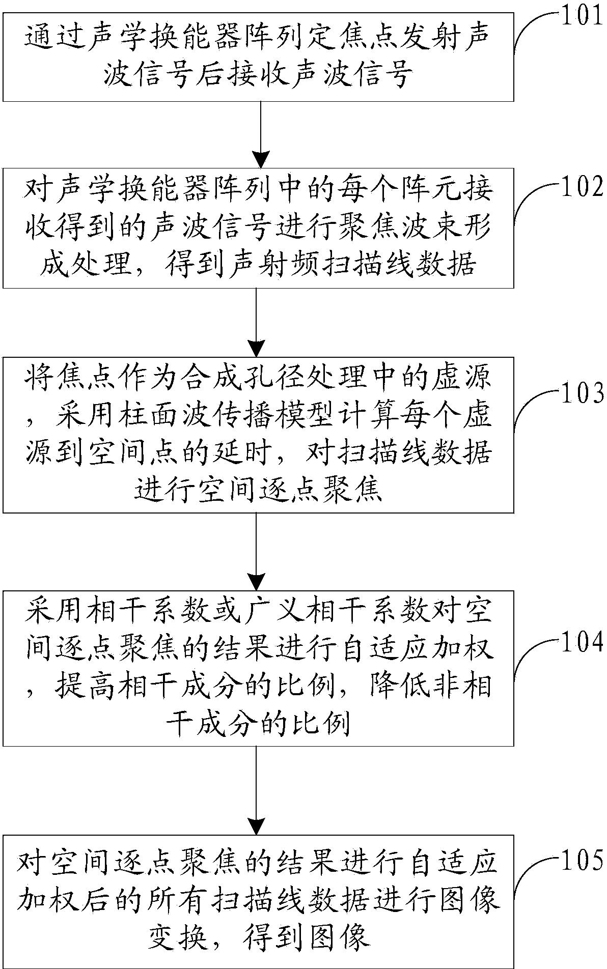
[0047] figure 1 It is a flow chart of the adaptive acoustic imaging method in Embodiment 1 of the present invention, such as figure 1 As shown, the adaptive acoustic imaging method specifically includes the following steps:

[0048] Step 101, transmit the acoustic wave signal through the fixed point of the acoustic transducer array and then receive the acoustic wave signal.

[0049] Since the acoustic signal received by the acoustic transducer is derived from the acoustic signal emitted by the acoustic transducer, in conventi...


PUM


Abstract

The invention relates to a self-adaptive acoustic imaging method. The method includes the steps that acoustic wave signals are received after being transmitted at fixed focuses through an acoustic transducer array; focusing beamforming processing is carried out on the acoustic wave signals received by each array element in the acoustic transducer array to obtain acoustic radio frequency scanning line data; the focuses are used as virtual sources in synthetic aperture processing, tine delay from each virtual source to the spatial point is calculated by means of a cylindrical wave propagation model, and spatial point-by-point focusing is carried out on the scanning line data; self-adaptive weighting is conducted on the result of the spatial point-by-point focusing by the adoption of correlation coefficients or generalized correlation coefficients, the proportion of coherent components is increased, and the proportion of incoherent component is reduced; image transformation is carried out on all the scanning line data after self-adaptive weighting conducted on the result of the spatial point-by-point focusing to obtain images. According to the method, the lateral resolution and contrast ratio which are identical in depth are achieved, the number of sidelobes is effectively reduced, and therefore all-round improvement in acoustic imaging quality is achieved.

Description

technical field [0001] The invention relates to an acoustic array imaging technology, in particular to an adaptive acoustic imaging method. Background technique [0002] Synthetic aperture acoustic imaging is derived from synthetic aperture radar technology. Synthetic Transmitting Aperture Imaging (STAI) method can improve frame rate, signal-to-noise ratio and contrast compared with conventional acoustic imaging method and other synthetic aperture imaging methods. However, STAI has high requirements on imaging equipment hardware, especially on data transmission and processing speed, which limits the commercialization of synthetic aperture acoustic imaging to a certain extent. At the same time, there are still problems such as insufficient energy of transmitting array elements and too many times of transmitting in synthetic transmitting aperture imaging. The strategy of fixed-focus transmission and dynamic focus in reception in conventional acoustic imaging makes the image ...

Claims


Application Information

Patent Timeline
IPC IPC(8): G01S15/89
CPCG01S15/8904G01S7/539
Inventor 吴文焘李平肖灵李遥韩晓丽张云翼
Owner INST OF ACOUSTICS CHINESE ACAD OF SCI
Learn More