Long-focus type panoramic annular imaging lens

A telephoto, annular lens technology, applied in the direction of optical components, optics, instruments, etc., can solve the problems of light energy loss, unfavorable protective glass, filter installation, relative aperture and small vertical field of view, etc., to achieve large vertical Field of view and relative aperture, improved uniformity of illumination on the image plane, good structure and manufacturability

Inactive Publication Date: 2014-08-06
CHINA JILIANG UNIV
View PDF9 Cites 8 Cited by
  • Summary
  • Abstract
  • Description
  • Claims
  • Application Information

AI Technical Summary

Problems solved by technology

However, there are essential deficiencies: (1) the first refraction surface and the first reflection surface of the panoramic annular lens are free-form surfaces, which are more difficult to process than spherical surfaces, and the PMMA engineering plastics used have a large thermal expansion coefficient and poor surface hardness, which is easy to (2) The radius of curvature of the first surface of the last lens is relatively small, and the off-axis light enters the lens at a large incident angle, and too much light energy is lost, reducing the illumination of the image surface, which is not conducive to the improvement of imaging quality improve
In addition, the last lens is similar to a plano-convex lens with a relatively large thickness, which increases the weight and cost of the lens; (3) the relative aperture and vertical field of view of the panoramic imaging lens are small, and the optical performance needs to be further improved; (4) the rear of the system The working distance is short, which is not conducive to the installation of protective glass, optical filters and other mechanical structures

Method used


Image

  • Long-focus type panoramic annular imaging lens
  • Long-focus type panoramic annular imaging lens
  • Long-focus type panoramic annular imaging lens

Examples


Embodiment Construction

[0026] The present invention will be described in further detail below in conjunction with the accompanying drawings. The following examples are helpful to the understanding of the present invention and are better application examples, but should not be regarded as a limitation of the present invention.

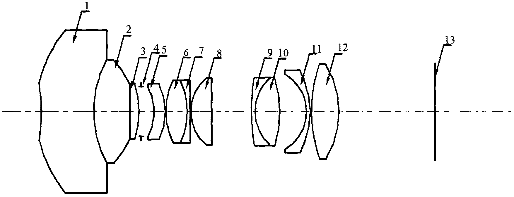
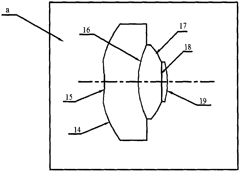
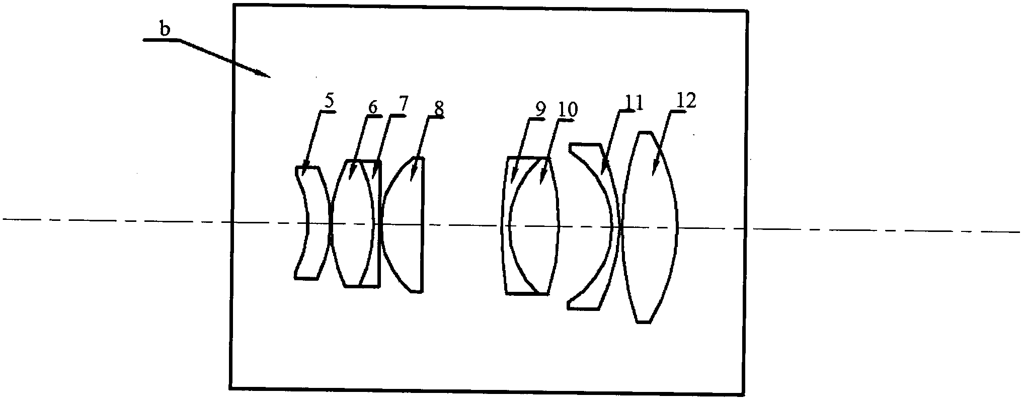
[0027] Such as figure 1 As shown, the present invention is a telephoto panoramic annular imaging lens, which includes a panoramic annular lens group a and a transfer lens group b. The panoramic annular lens group a includes a first lens 1 , a second lens 2 and a third lens 3 arranged coaxially and sequentially from the object side to the image side. Panoramic annular lens group a adopts a special triple cemented panoramic annular lens structure. Relay lens group b includes 8 lenses, including 1 negative meniscus lens, 1 positive lens, and 2 doublet lenses.

[0028] The diaphragm 4 is located between the panoramic annular lens group a and the relay lens group b, and is used ...


PUM


Abstract

The invention provides a long-focus type panoramic annular imaging lens. The long-focus type panoramic annular imaging lens is totally composed of eleven spherical lenses, and comprises a panoramic annular lens assembly and a transferring lens assembly. The panoramic annular lens assembly comprises a first lens, a second lens and a third lens coaxial and arranged sequentially from an object space to an image space, and is of a triplet panoramic annular lens structure. The transferring lens assembly is composed of eight lens including a negative meniscus lens, a positive lens and two doublets. The long-focus type panoramic annular imaging lens satisfies f-theta object-image relation, and has the advantages of high resolution, super large field of view (360 degrees in the horizontal direction and 60 degrees in the vertical direction), high imaging quality and the like; adopted glass is ordinary optical glass excluding special glass and calcium fluoride; the lens structure is good in manufacturability to the benefit of processing and reduction of cost.

Description

technical field [0001] The invention belongs to the technical field of optical imaging lenses, and relates to a telephoto panoramic annular imaging lens, in particular to a telephoto lens with high resolution, (40°-100°)×360° super large field of view and good imaging quality. Focus type panoramic ring lens. Background technique [0002] At present, the existing wide-angle imaging lens cannot meet the requirements of 360° all-round acquisition of target information. Early panoramic imaging was basically realized by the rotation stitching method. Rotary mosaic method includes single-lens rotational scanning imaging and multi-lens staring imaging. Single-lens rotary scanning imaging refers to the use of a single ordinary optical lens to rotate around a mechanical axis perpendicular to the optical axis for panoramic scanning, and then seamlessly stitching through image stitching software to obtain panoramic images. However, there is a scanning period in single-lens rotary sc...

Claims


Application Information

Patent Timeline
Patent Type & Authority Applications(China)
IPC IPC(8): G02B13/06
Inventor 李劲松孟娜冯科
Owner CHINA JILIANG UNIV
Why Eureka
Try Eureka