Light machine device of rear-projection television

A technology of TV and optical machine, which is applied in the direction of TV, color TV parts, TV system parts, etc. It can solve the problems of not being able to adapt to thinness, difficulty in development, and large volume of light source, so as to achieve thinning and volume reduction Effect

Inactive Publication Date: 2014-08-06
HONG FU JIN PRECISION IND (SHENZHEN) CO LTD +1
View PDF3 Cites 0 Cited by
  • Summary
  • Abstract
  • Description
  • Claims
  • Application Information

AI Technical Summary

Problems solved by technology

Due to problems such as the large volume of the light source, the long projection distance of the projection lens, and the relative arrangement of the reflectors, the above-mentioned optical-mechanical device cannot adapt to the development of electronic products in recent years. "trend, resulting in said product development has its shortcomings and difficulties to be overcome

Method used


Image

  • Light machine device of rear-projection television
  • Light machine device of rear-projection television
  • Light machine device of rear-projection television

Examples


Embodiment Construction

[0012] The present invention will be described in detail below in conjunction with the accompanying drawings.

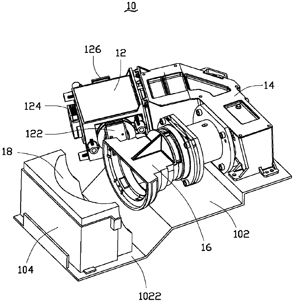
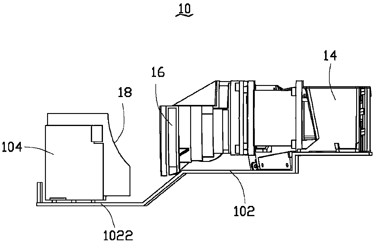
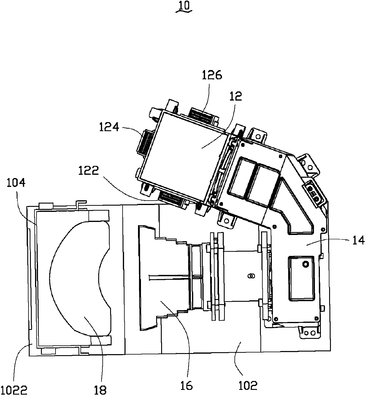
[0013] see figure 1 , is a schematic diagram of an embodiment of an optical-mechanical device of a rear-projection television according to the present invention. The optical-mechanical device 10 includes a light source 12 , an optical assembly 14 , a short-focus lens 16 and a curved mirror 18 . The light source 12 is a solid-state light source or a solid-state light source module, the solid-state light source is a light emitting diode (Light Emitting Diode, LED) or a laser diode (Laser Diode, LD), and the light source 12 uses a solid-state light source or a solid-state light source The module is used to reduce the excessive volume of the current projection light bulb. In this embodiment, the light source 12 is a solid-state light source module of LEDs, which has a red LED 122 , a green LED 124 and a blue LED 126 for providing three primary colors of light. The ligh...


PUM


Abstract

The invention provides a light machine device of a rear-projection television. The light machine device comprises a light source, an optical assembly, a short-focus lens and a curved mirror. The light source and the short-focus lens are arranged on a bearing plate side by side, the light source is connected with the short-focus lens through the optical assembly, the curved mirror is arranged at the front end of the short-focus lens, and the relative positions of the short-focus lens and the curved mirror are stabilized through a fixing base arranged on the bearing plate. According to the light machine device of the rear-projection television, the relative positions of the short-focus lens and the curved mirror are set so that the projection distance can be reduced and the thinning design of the rear-projection television can be facilitated.

Description

technical field [0001] The invention relates to an optical-mechanical device of a rear-projection TV, in particular to an optical-mechanical device of a rear-projection TV that shortens the projection distance and thins the thickness of the casing. Background technique [0002] The image display of a general rear-projection TV mainly generates a projection beam with image information through the operation of an optomechanical device, and then projects the projection beam onto a display screen through a projection lens and a reflector. Wherein, the projection light beam is the light beam generated by the light source of the optomechanical device, which is formed after being optimized and processed by an optical component. Or xenon lamps, etc., although they have high brightness, their common feature is that they are too large. In addition, in order to avoid distortion of the projected image, the projection lens mostly adopts a telecentric lens, and the telecentric lens needs...

Claims


Application Information

Patent Timeline
Patent Type & Authority Applications(China)
IPC IPC(8): G03B21/28G03B21/14H04N5/74
Inventor 叶文彬邱崇哲黄凯
Owner HONG FU JIN PRECISION IND (SHENZHEN) CO LTD
Why Eureka
Try Eureka