Direct Backlight Module

Active Publication Date: 2015-07-23
TCL CHINA STAR OPTOELECTRONICS TECH CO LTD
View PDF5 Cites 0 Cited by
  • Summary
  • Abstract
  • Description
  • Claims
  • Application Information

AI Technical Summary

Benefits of technology

The present invention provides a direct backlight module for liquid crystal display devices that has a simple structure and low cost. This backlight module has improved utilization rate of light energy by using light guide plates between LED light bars, which reduces the number of LED lights needed and manufacturing costs. The arrangement of the light guide plates also enhances homogeneity of light illumination and reduces the thickness of the backlight module, making it easier to thin the display device.

Problems solved by technology

However, a backlight module using LED as a light source has a thickness that is more than two times of that of a backlight module using CCFL as a light source, making it disadvantageous for thinning of liquid crystal display device.

Method used


Image

  • Direct Backlight Module
  • Direct Backlight Module
  • Direct Backlight Module

Examples


Embodiment Construction

[0031]To further expound the technical solution adopted in the present invention and the advantages thereof, a detailed description is given to a preferred embodiment of the present invention and the attached drawings.

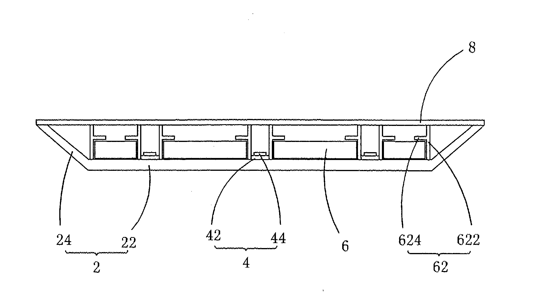
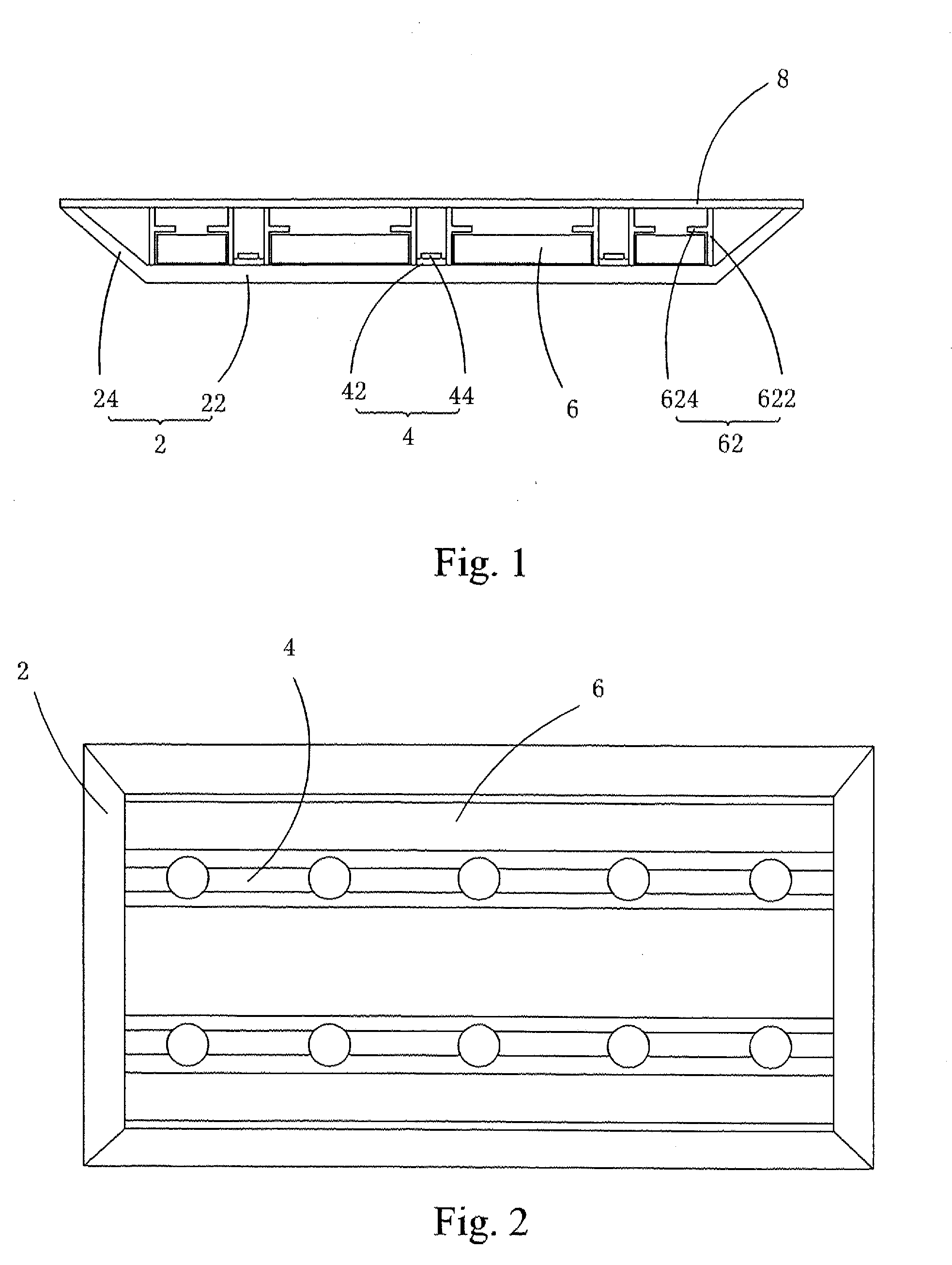
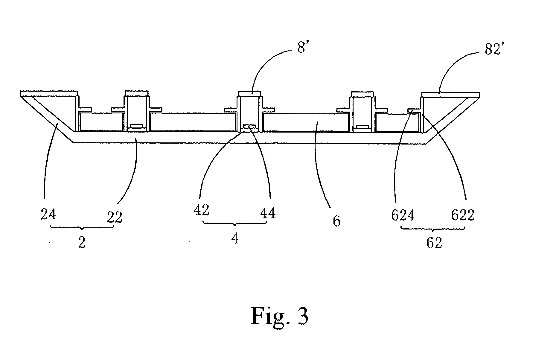
[0032]Referring to FIGS. 1 and 2, the present invention provides a direct backlight module, which comprises a backplane 2, a plurality of LED light bars 4 mounted on the backplane 2, a plurality of light guide plates 6 alternately arranged with respect to the LED light bars 4, and a diffusion plate 8 mounted on the backplane. Due to the arrangement of the light guide plates 6, light mixing distance for the light emitting from the LED light bars 4 is extended so as to enhance the effect of light mixing and improve homogeneity of illumination and also improve utilization rate of the light emitting from the LED light bars and effectively lower down cost.

[0033]The backplane 2 comprises a bottom board 22 and side boards 24 connected to the bottom board 22.

[0034]The LED ligh...


PUM


Abstract

The present invention provides a direct backlight module, which includes a backplane, a plurality of LED light bars retained on the backplane, a plurality of light guide plates arranged alternate with respect to the LED light bars, and a diffusion plate mounted on the backplane. The direct backlight module includes the light guide plates that are arranged between the LED light bars to improve utilization rate of light energy of the LED light bars so as to reduce the number of LED lights included in the LED light bars to thereby reduce the manufacturing cost. Further, the arrangement of the light guide plates effectively shortens the light mixing distance and enhances homogeneity of light illumination and also reduces the thickness of backlight module to thereby facilitate thinning of a liquid crystal display device.

Description

BACKGROUND OF THE INVENTION[0001]1. Field of the Invention[0002]The present invention relates to the field of liquid crystal displaying, and in particular to a direct backlight module.[0003]2. The Related Arts[0004]Liquid crystal display (LCD) has a variety of advantages, such as thin device body, low power consumption, and being free of radiation, and is thus widely used. Most of the LCDs that are currently available in the market are backlighting LCDs, which comprise a liquid crystal panel and a backlight module. The operation principle of the liquid crystal panel is that liquid crystal molecules are interposed between two parallel pieces of glass and a plurality of vertical and horizontal fine electrical wires is arranged between the two pieces of glass, whereby the liquid crystal molecules are controlled to change direction by application of electricity in order to refract out light emitting from the backlight module for generating images. Since the liquid crystal panel itself d...

Claims


Application Information

Patent Timeline
IPC IPC(8): G02F1/1335
CPCG02F1/133608G02F1/133603G02F1/133524G02F1/133609G02F1/133611G02F1/133606G02B6/0025G02B6/0078G02B6/0088
Inventor WANG, YEWEN
Owner TCL CHINA STAR OPTOELECTRONICS TECH CO LTD
Why Eureka
Try Eureka