
Fireproof bus duct

A fire-resistant busway and fire-resistant technology, applied in the direction of cooling busbar devices, fully enclosed busbar devices, etc., can solve problems such as fire, short service life of conductive bars, spontaneous combustion of busway, etc., to improve fire performance, thermal conductivity, and material uniform effect

Active Publication Date: 2014-08-06
江苏瑞欧宝电气股份有限公司
View PDF6 Cites 17 Cited by
  • Summary
  • Abstract
  • Description
  • Claims
  • Application Information

AI Technical Summary

Problems solved by technology

This type of fire-resistant busway is widely used in key projects such as power transmission trunks for fire-fighting equipment. Causing a fire will cause very serious losses in a densely populated building with a large power consumption
[0003] The traditional busway has poor fire performance. Its structure consists of upper cover, lower cover and side panels, which are fixedly connected to form an external shell, and the conductive bar is fixed in the shell. It is difficult to dissipate the heat inside the slot, the service life of the conductive bar is short, and the heat on the SLR conductive bar cannot be discharged in time. When it reaches a certain high temperature, the bus duct will spontaneously ignite and cause a fire; at the same time, the current bus duct has poor fire resistance. In a fire, it is easy to be ignited by fire, resulting in interruption of power supply, which brings great obstacles to fire rescue

Method used


Image

  • Fireproof bus duct

Examples


Embodiment Construction

[0022] The present invention will be further explained below in conjunction with the accompanying drawings and specific embodiments. It should be understood that the following specific embodiments are only used to illustrate the present invention but not to limit the scope of the present invention.

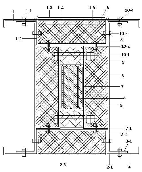
[0023] It can be seen from the accompanying drawings that the upper cover plate 1 and the lower cover plate 2 of the busway of the present invention are respectively fixed with the outer flanges 3-1 of the two parallel outer plates 3 by bolts 10-4, and the heat conducting upper curved plate 1-1 The concave groove 1-2 and the arch 2-2 of the heat conduction lower curved plate 2-1 are both embedded between the two outer plates 3, and the side walls of the concave groove 1-2 and the arch 2-2 are respectively passed through bolts 10-3 It is fixed with the outer plate 3, and the refractory aluminum silicate cotton felt 5 is filled in the recessed groove 1-2, and a layer of fire-resista...


PUM


Abstract

The invention discloses a fireproof bus duct. An upper cover board comprises an upper heat conduction bending board with a concave groove and a heat dissipating board on the concave groove. The heat dissipating board is provided with heat dissipating holes, a top cover is arranged on the heat dissipating board, and a certain sealing space is formed between the top cover and the heat dissipating board. A lower cover board comprises a lower heat conduction bending board with an arch and a bottom board located at the bottom of the arch. The concave groove and the arch are embedded between outer side boards. A conducting bar is arranged between the concave groove and the arch, the left side and the right side of the conducting bar are provided with inner side boards, fireproof insulating cushion blocks are arranged on the upper portion and the lower portion of the conducting bar, fireproof aluminum silicate wool felt and fireproof boards are arranged between the inner side boards and the corresponding outer side boards, in concave groove and on the arch, and a conducting strip of the conducting bar is covered with a mica tape. According to the fireproof bus duct, the heat produced by the conducting bar can be dissipated in time, the spontaneous combustion of the conducting bar due to the high temperature is avoided, and the service life of the bus duct is prolonged; the bus duct has good fireproof performance, and even when the outside breaks out the fire, the conducting bar cannot be burned, and the bus duct can still normally supply power.

Description

technical field [0001] The invention relates to a fire-resistant busway, which belongs to the field of power transmission equipment. Background technique [0002] With the rapid development of the city, there are more and more high-rise buildings, the phenomenon of dense population in high-rise buildings is obvious, and the electricity load has increased sharply. The increase in electricity load will inevitably bring fire hazards, and it is of great significance to prevent the occurrence of electricity fires. At present, the fire-resistant busbars on the market are mainly composed of refractory aluminum silicate cotton felt and fire-resistant coatings. In this way, only the fire-resistant performance of the busbar is emphasized, but its heat dissipation performance is ignored. This type of fire-resistant busway is widely used in key projects such as power transmission trunks for fire-fighting equipment. Causing a fire will cause very serious losses in a densely populated bu...

Claims


Application Information

Patent Timeline
IPC IPC(8): H02G5/06H02G5/10
CPCH02G5/10
Inventor 林月珍顾旭梅顾红卫姚建明王勇王之昂唐娉婷何柏群
Owner 江苏瑞欧宝电气股份有限公司
Learn More