
Permanent magnet synchronous motor device with closed self-circulation cooling system for stator

A permanent magnet synchronous motor and cooling system technology, which is applied in the electrical field, can solve the problems of surface temperature rise and uneven temperature distribution of the solid rotor of permanent magnet motors, and achieve good cooling effect, weaken the influence, and reduce the effect of working temperature rise

Active Publication Date: 2014-08-06
江苏利得尔电机有限公司
View PDF5 Cites 4 Cited by
  • Summary
  • Abstract
  • Description
  • Claims
  • Application Information

AI Technical Summary

Problems solved by technology

[0004] The present invention aims at the problem that the surface temperature rise of the solid rotor of the permanent magnet motor is high and the temperature distribution is unbalanced, so that the temperature of the permanent magnet is too high to demagnetize, and a permanent magnet synchronous motor device with a closed self-circulating cooling system for the stator is proposed. Improve the working stability of the permanent magnet in the motor and the whole motor

Method used


Image

  • Permanent magnet synchronous motor device with closed self-circulation cooling system for stator
  • Permanent magnet synchronous motor device with closed self-circulation cooling system for stator
  • Permanent magnet synchronous motor device with closed self-circulation cooling system for stator

Examples


Embodiment 1

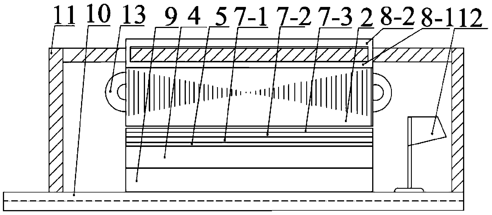
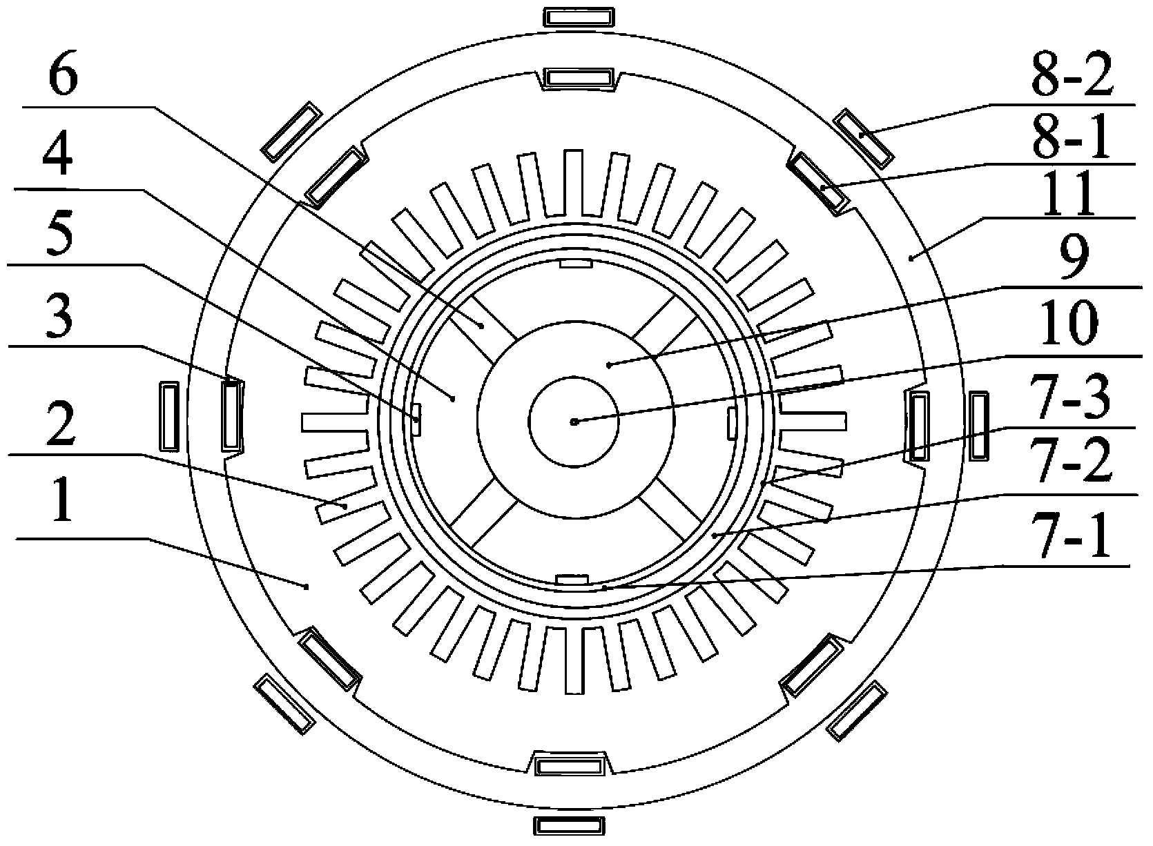
[0017] Embodiment 1: as figure 1 and figure 2 As shown, stator winding slots 2 are evenly distributed along the circumference on the inner side of the stator core 1, and stator ventilation grooves 3 are evenly distributed along the circumference on the outer side of the stator core 1; the number of stator ventilation grooves is 8; the permanent magnet 6 adopts 4 poles , embedded in the rotor core 4 or surface-attached on the rotor core 4; the magnetic isolation ring 9 is keyed to the motor shaft 10; the number of rotor ventilation grooves 5 is 4; the cooling pipe 8 is along the shaft The angle of inclination is 3°-5°. The fan exchanges heat with the cooling liquid in the cooling pipe in the casing, the cooling liquid in the cooling pipe is heated, and after evaporation, the cooling liquid flows to the cooling pipe outside the casing, such as image 3 Indicated by the solid arrow. The cooling pipe outside the casing communicates with the inside and is opposite to the flow d...


PUM


Abstract

The invention particularly relates to a permanent magnet synchronous motor device with a closed self-circulation cooling system for a stator, and belongs to the field of electrical technologies. The permanent magnet synchronous motor device comprises a motor shaft and a rotor core. The rotor core sleeves the motor shaft, a non-magnetic ring is arranged between the motor shaft and the rotor core, a stator core sleeves the rotor core, a vacuum jacket is arranged between the rotor core and the stator core, a housing case sleeves the stator core, and cooling pipes are respectively arranged on the inner side and the outer side of the housing case. The permanent magnet synchronous motor device has the advantages that the permanent magnet synchronous motor device is provided with the vacuum jacket of a rotor, so that heat generated due to eddy-current loss on the surface of the rotor can be effectively stopped against being transmitted to permanent magnets; heat inside a motor can be quickly carried away by the closed self-circulation cooling system for the stator, so that temperature rise of the motor can be reduced, influence of high temperature rise on demagnetization of the permanent magnets can be decreased, the service lives of the permanent magnets and the service life of the motor can be prolonged, and the overload capacity of the motor can be improved.

Description

technical field [0001] The invention specifically relates to a permanent magnet synchronous motor device whose stator adopts a closed self-circulation cooling system, and belongs to the field of electrical technology. Background technique [0002] Because permanent magnet motors do not need excitation windings and excitation power supplies, they have simple structure, low loss, high efficiency, and high power density. With its unique advantages, permanent magnet motors have good application prospects in aerospace, machining, shipbuilding and military fields. [0003] Compared with conventional motors, permanent magnet motors have a magnetic field generated by permanent magnets. Due to different driving methods and the influence of pole slots, permanent magnet motor rotors will generate losses, which are concentrated in the magnetic poles and rotor yoke surface areas, thus As a result, the heat source density in this area is relatively high, causing the rotor to heat up. In...

Claims


Application Information

Patent Timeline
Patent Type & Authority Applications(China)
IPC IPC(8): H02K21/14H02K5/20H02K1/20H02K1/32H02K9/06
Inventor 李伟力李金阳张晓晨开志宏曹君慈李佳友王聪
Owner 江苏利得尔电机有限公司
Learn More