
Artificial limb knee joint of gear five-bar mechanism

A knee joint and link mechanism technology, applied in the field of prosthetic knee joints, can solve problems such as the inability to adjust the patient's gait, the inability to freely adjust the parameters of the knee joint, and the inability to fully achieve the kinematic performance of the human knee joint.

Active Publication Date: 2014-08-13
NORTHWESTERN POLYTECHNICAL UNIV
View PDF9 Cites 10 Cited by
  • Summary
  • Abstract
  • Description
  • Claims
  • Application Information

AI Technical Summary

Problems solved by technology

The motion parameters of the traditional four-bar mechanism prosthetic knee joint are fixed after installation, and the patient's gait cannot be adjusted by changing its own related parameters.
At the same time, due to the fixity of the four-bar mechanism and the limitation of its own motion law, the motion parameters of the knee joint are fixed after the specific installation, and cannot be adjusted to meet different needs.
Moreover, there are still some defects in the bionic performance of the four-bar mechanism, which cannot fully achieve the kinematic performance of the human knee joint.
[0003] In the Chinese patent CN201806805, the mechanism consists of an upper joint body, a lower joint body, a front rod located on the outside, and a rear connecting rod located on the inside; Knee joint parameters cannot be freely adjusted after implementation
[0004] In the patent CN202665757, its structure is composed of connecting rod head, front connecting rod, rear connecting rod, main connecting rod, supporting connecting rod, connecting rod body and oil cylinder; this structure also cannot freely adjust knee joint parameters after installation and implementation

Method used


Image

  • Artificial limb knee joint of gear five-bar mechanism

Examples


Embodiment Construction

[0014] This embodiment is a prosthetic knee joint of a gear five-bar mechanism.

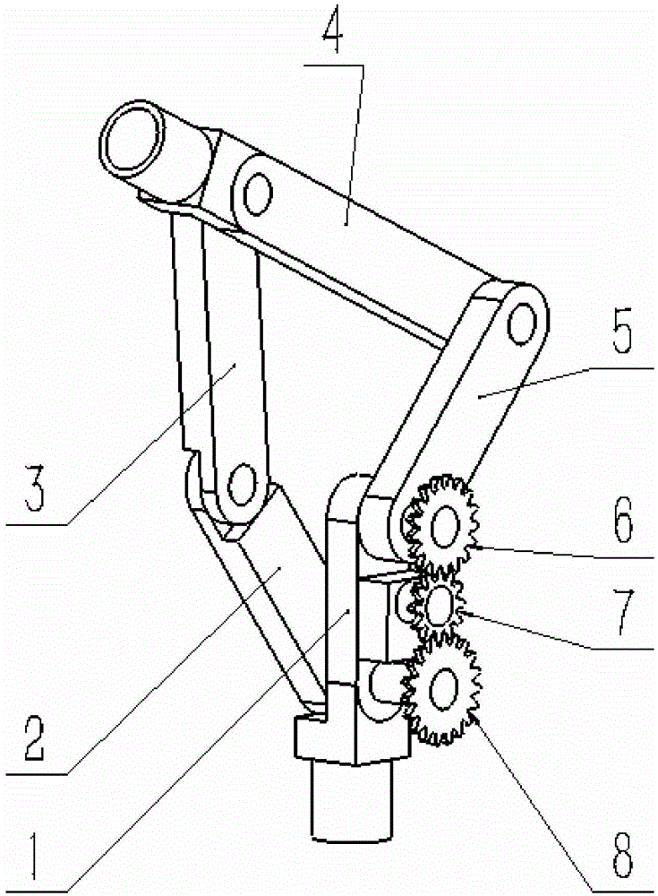
[0015] refer to figure 1 , the prosthetic knee joint of the gear five-bar mechanism in this embodiment is composed of a link mechanism and a gear mechanism. The link mechanism is connected end to end by five links. side of the rod mechanism.

[0016] The link mechanism includes calf link 1, rear control rod 2, support rod 3, thigh link 4, and front control bar 5. The calf link 1 is used as the frame, and the lower end connection port of the calf link 1 is fixedly connected to the lower leg of the prosthesis. , the connecting port at the upper end of the thigh connecting rod 4 is connected with the connecting device of the thigh socket, and the thigh connecting rod 4 and the calf connecting rod 1 are in the same plane in space. The front control rod 5 is installed on the right side of the shank link 1 and the thigh link 4, the lower end of the front control bar 5 is hinged with the upper end of ...


PUM


Abstract

The invention relates to an artificial limb knee joint of a gear five-bar mechanism, comprising a gear mechanism and a link mechanism, wherein the link mechanism consists of five links in head-to-tail ligation; the gear mechanism is fixedly connected with the links by a revolving shaft; a calf link serves as the rack; the connector in the lower end of the calf link is fixedly connected to an artificial limb calf; the connector in the upper end of a thigh link is connected to a thigh socket connecting device; the thigh link and the calf link are in the same plane in space; the five links form a closed-loop structure; the gear mechanism is located on one side of the link mechanism; a intermediate control gear is meshed with an upper control gear and a lower control gear; the intermediate control gear is fixed on the revolving shaft; the other end of the revolving shaft is fixedly connected with a micro transmission; the transmission is connected with a motor; the motor supplies power to realize the stability control of the stance phase and the swing phase of the artificial limb knee joint. The artificial limb knee joint of the gear five-bar mechanism realizes the regulation of an instantaneous center and adaptive damping by means of gear ratio regulation by using the motion characteristics of the gear five-bar mechanism.

Description

technical field [0001] The invention relates to a prosthetic knee joint for one-leg or double-leg above-knee amputation, in particular to a prosthetic knee joint with a gear five-bar mechanism. Background technique [0002] For people with physical disabilities, prosthetics have become an indispensable functional replacement device. After the stump that was originally amputated is installed with a prosthesis, it can realize the basic functions that have been lost. The prosthetic knee joint is the core part of the lower prosthesis, and its function directly affects the overall function of the lower prosthesis. The existing prosthetics on the market are mainly a small number of single-axis knee joints and a large number of multi-axis knee joints of four-bar mechanism; single-axis knee joints are gradually eliminated due to lack of bionic performance. The four-bar mechanism has been widely used due to its relatively good biomimetic performance. After the traditional four-bar...

Claims


Application Information

Patent Timeline
Patent Type & Authority Applications(China)
IPC IPC(8): A61F2/38
Inventor 葛文杰孙园喜郑佳董典彪
Owner NORTHWESTERN POLYTECHNICAL UNIV
Learn More