Large-stroke high-energy-dissipation shape memory alloy buffer

A memory alloy and buffer technology, applied in the direction of low internal friction spring, etc., can solve the problems of limited application scope, complex structure, buffer stroke dependent on the length of alloy wire, etc., to achieve high material utilization, high energy dissipation capacity, Conducive to the effect of buffer protection

Inactive Publication Date: 2014-08-13
UNIV OF SCI & TECH OF CHINA
View PDF6 Cites 13 Cited by
  • Summary
  • Abstract
  • Description
  • Claims
  • Application Information

AI Technical Summary

Problems solved by technology

[0005] According to its material characteristics, various devices using shape memory alloys for buffering and energy dissipation have emerged, among which the mainstream is the stretching mechanism using alloy wires, but the buffer strokes of these devices depend heavily on the length of alloy wires, and the relative deformation is biased. small, limited range of application
Recently, the inventor applied to the State Intellectual Property Office for an invention patent "a hydraulic buffer device using a shape memory alloy", patent application number 201410126824.3, using uniaxial stretching of a pseudoelastic shape memory alloy rod for energy consumption and reset , through the area ratio of the large piston and the small plunger in the hydraulic device, the function of displacement amplification is realized, but it involves hydraulic pressure, sealing and other devices, and the structure is slightly complicated

Method used


Image

  • Large-stroke high-energy-dissipation shape memory alloy buffer
  • Large-stroke high-energy-dissipation shape memory alloy buffer
  • Large-stroke high-energy-dissipation shape memory alloy buffer

Examples


Embodiment Construction

[0028] The specific implementation manners of the present invention will be described in detail below in conjunction with the technical solutions and with reference to the accompanying drawings.

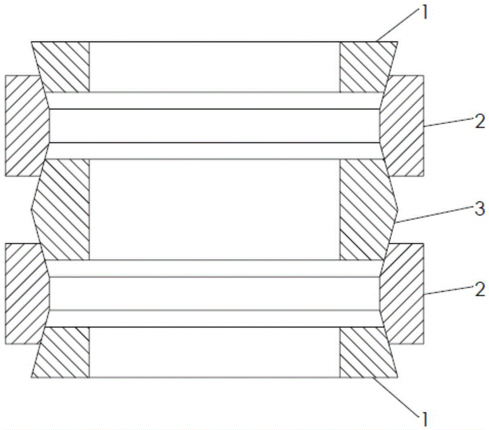
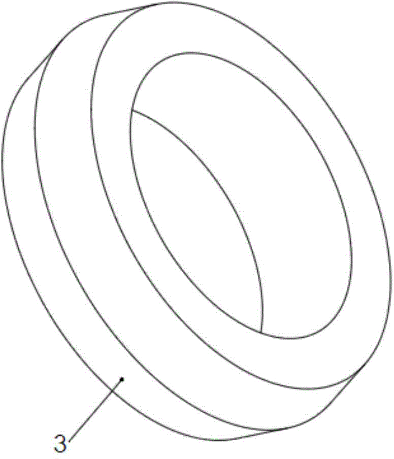
[0029] An embodiment of a basic model of the patent of the present invention, such as figure 1 As shown, it includes three parts: a single-cone inner ring 1, a double-cone inner ring 3, and a shape-memory alloy outer ring 2 with double inner cones. According to the needs of the actual stroke, the logarithm of the inner and outer rings can be selected and assembled by overlapping. The two ends are single-cone inner rings 1, and the middle is several shape-memory alloy outer rings with double inner cones. 2 and double-cone inner rings 3 are alternately arranged.

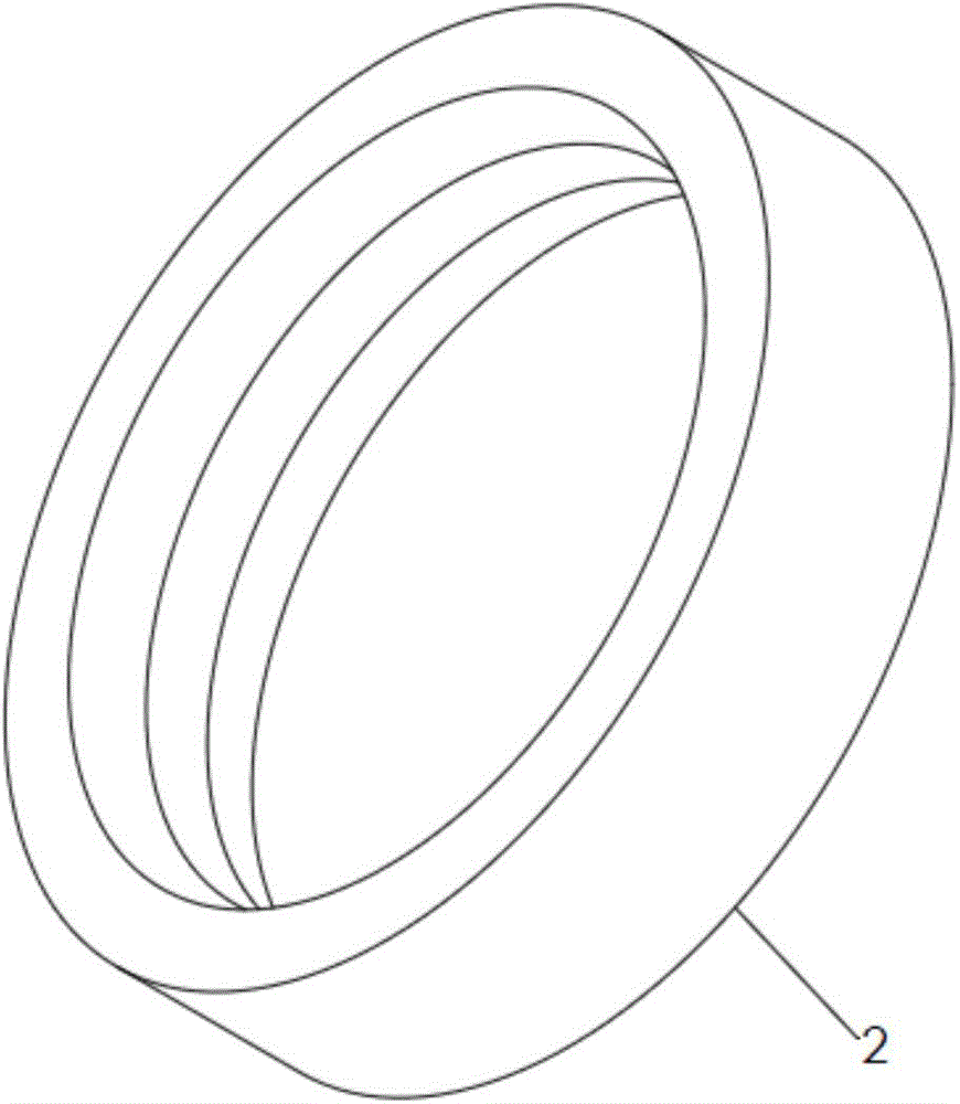
[0030] The taper angles of the inner and outer rings are equal, preferably between 12° and 20°. A shape memory alloy outer ring 2 with double inner cones, its structure is as follows figure 2 As shown, the outer surface i...


PUM


Abstract

The invention relates to a buffer device applied to the fields of vehicles, machinery and the like, in particular to a buffer device which utilizes a shape memory alloy material and has the characteristics of large stroke, high energy dissipation, resettability and the like. The buffer device comprises single-conical-surface inner circular rings, a double-conical-surface inner circular ring and double inner conical surface-containing shape memory alloy outer circular rings, wherein the single-conical-surface inner circular rings are arranged at the two ends of the buffer device respectively, and a plurality of double inner conical surface-containing shape memory alloy outer circular rings and the double-conical-surface inner circular ring are arranged in the middle of the buffer device alternately. The buffer device is simple in structure and convenient to process and assemble. The shape memory alloy material is in an annular stretch state, the stress state is simple and uniform, and the material utilization rate is high. Compared with the traditional annular spring buffer, the buffer device has the advantage that the relative compression deformation is obviously improved. The energy dissipation through shape memory alloy phase change is combined with the energy dissipation through friction, so that the energy dissipation capability is higher. When the compression displacement is relatively large, the load is almost kept constant, and buffer protection is favorably realized.

Description

technical field [0001] The invention relates to a buffer device suitable for vehicles, machinery and other fields, in particular to a buffer device using a shape memory alloy material, which has the characteristics of large stroke, high energy consumption, resettable and the like. Background technique [0002] Buffer devices are widely used in machinery, vehicles and earthquake-resistant buildings. According to the relationship between the buffer and the speed and displacement, it can be roughly divided into speed type, displacement type and hybrid type buffer. Speed-type shock absorbers, such as common hydraulic shock absorbers, have a large difference in force at different impact speeds. When the speed exceeds a certain speed limit, the buffer force will be too large. The device that utilizes the principle of metal plastic deformation to buffer energy consumption belongs to the displacement type buffer. It is widely used in the fields of automobile anti-collision and buil...

Claims


Application Information

Patent Timeline
Patent Type & Authority Applications(China)
IPC IPC(8): F16F3/02
Inventor 张科唐志平
Owner UNIV OF SCI & TECH OF CHINA
Why Eureka
Try Eureka