Light locating system and method used for cleaning robot

A cleaning robot and optical positioning technology, which is applied to the optical positioning system of the cleaning robot and its positioning field, can solve the problems of the difficulty of positioning the position sensor, the irregular placement of furniture, the positioning error, etc., so as to reduce the burden of housework and the positioning method is simple. The effect of convenience and high positioning accuracy

Inactive Publication Date: 2014-08-13
SUZHOU LUXCOM PHOTOELECTRIC TECH
View PDF6 Cites 16 Cited by
  • Summary
  • Abstract
  • Description
  • Claims
  • Application Information

AI Technical Summary

Problems solved by technology

Existing cleaning robots use position sensors for positioning. However, due to the irregular placement of furniture and other objects in ordinary households, it brings certain difficulties to the positioning of position sensors. Positioning errors often occur and leakage occurs.

Method used


Image

  • Light locating system and method used for cleaning robot
  • Light locating system and method used for cleaning robot
  • Light locating system and method used for cleaning robot

Examples


Embodiment

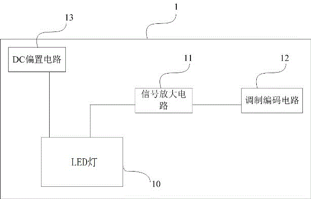
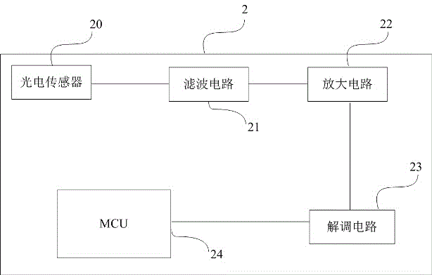
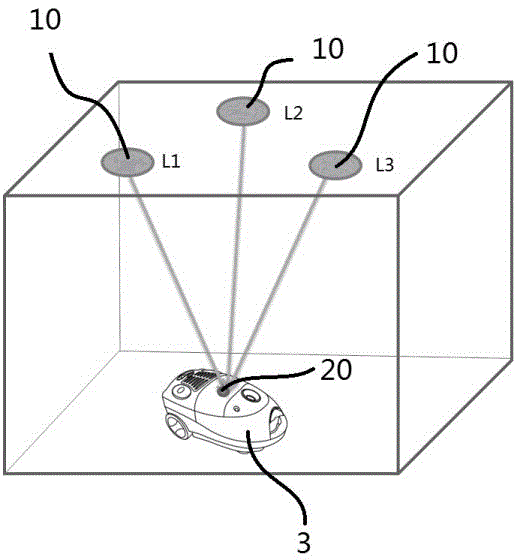
[0036] A kind of LED positioning system for cleaning robot of this embodiment, such as Figure 1 ~ Figure 2 As shown, it includes: LED emitting device 1, LED emitting device 1 includes a plurality of LED lamps 10 ( figure 1 Only one LED light is schematically shown in the figure), each LED light 10 loads its own identification code into the optical signal for transmission, and the identification code is the position information of the LED light 10 in the LED emitting device 1; it is set on the cleaning robot 3 The signal receiver 2 on the LED lamp 10 is used to receive the light signal from the LED lamp 10; the microcontroller (MCU) 24 is used to carry out the intensity and time of the light signals of at least three LED lamps 10 received by the signal receiver 2 Calculate and process to obtain the spatial position where the signal receiver 2 is located.

[0037] The LED emitting device 1 includes: an LED lamp 10, used to transmit an optical signal loaded with an identificati...


PUM


Abstract

The invention discloses a light locating system used for a cleaning robot. The light locating system comprises a light emitting device, a signal receiver arranged on the cleaning robot and a microcontroller. The light emitting device comprises a plurality of luminous sources, each luminous source loads a recognition code of itself into a light signal to be transmitted, and the recognition codes are position information of the luminous sources in the light emitting device. The signal receiver is used for receiving the light signals from the luminous sources. The microcontroller is used for conducting calculating processing on the strength and the time of the light signals, received by the signal receiver, of at least three of the luminous sources to obtain the spatial position of the signal receiver. According to the light locating system, the luminous sources realize an indoor locating function while being used for lighting, therefore, the indoor spatial position of the cleaning robot is determined and automatic cleaning work for preset specific lines is completed. A locating method is simple, convenient to implement and high in locating precision, and greatly reduces the housework burden of people.

Description

technical field [0001] The invention belongs to the field of optical communication technology and the field of household cleaning, and in particular relates to an optical positioning system and a positioning method for a cleaning robot. Background technique [0002] A cleaning robot is an electric cleaning device equipped with a microcomputer system, which can clean a specific part or all of the room according to people's settings. The positioning technology of the cleaning robot is the core technology of the entire cleaning robot. Existing cleaning robots use position sensors for positioning. However, due to the irregular placement of furniture and other objects in ordinary households, it is difficult to locate the position sensors. Positioning errors often occur, resulting in suction leakage. On the other hand, with the continuous promotion of LED environmental lighting technology, it is an irreversible trend for LED lighting systems to replace ordinary fluorescent lamps....

Claims


Application Information

Patent Timeline
Patent Type & Authority Applications(China)
IPC IPC(8): G01S5/16
CPCG01S5/16
Inventor 孙慧明王辉
Owner SUZHOU LUXCOM PHOTOELECTRIC TECH
Why Eureka
Try Eureka