Fully digital oxygen generator monitoring and control system

A monitoring and control, all-digital technology, applied in the field of all-digital oxygen generator monitoring and control systems, can solve the problem that the safety of oxygen generators does not have an effective and clear guarantee for the safety of users, and the maintenance personnel do not have a clear guide for fault judgment. The maintenance and repair time of the oxygen generator is prolonged, so as to achieve the effect of convenient and fast maintenance, ensuring the safety of use and improving the production efficiency

Active Publication Date: 2016-08-24
保定迈卓医疗器械有限公司
View PDF5 Cites 1 Cited by
  • Summary
  • Abstract
  • Description
  • Claims
  • Application Information

AI Technical Summary

Problems solved by technology

[0007] 4) Depending on the hardware to adjust the operating parameters of the oxygen generator, due to the drift of the resistance value with the temperature, it will inevitably affect the continuous high-concentration oxygen production capacity of the oxygen generator
[0008] To sum up, some of the functions included in these oxygen concentrators cannot meet the needs of the current market and the maintenance and protection of oxygen concentrators and users, so that users do not have a comprehensive understanding of oxygen concentrators. There is no effective and clear guarantee for safety and user safety. At the same time, there is no clear guidance for maintenance personnel to judge faults, which makes the maintenance and repair time of oxygen generators longer.
Moreover, the functions contained in the existing molecular sieve oxygen generators are not comprehensive enough, and the alarm function only stays at the level of sound and light alarms, and cannot digitally and intuitively display the relevant alarm information and digital adjustment parameters inside the oxygen generator to the user.

Method used


Image

  • Fully digital oxygen generator monitoring and control system
  • Fully digital oxygen generator monitoring and control system
  • Fully digital oxygen generator monitoring and control system

Examples


Embodiment Construction

[0029]Embodiments of the present invention are described in detail below, examples of which are shown in the drawings, wherein the same or similar reference numerals designate the same or similar elements or elements having the same or similar functions throughout. The embodiments described below by referring to the figures are exemplary and are intended to explain the present invention and should not be construed as limiting the present invention.

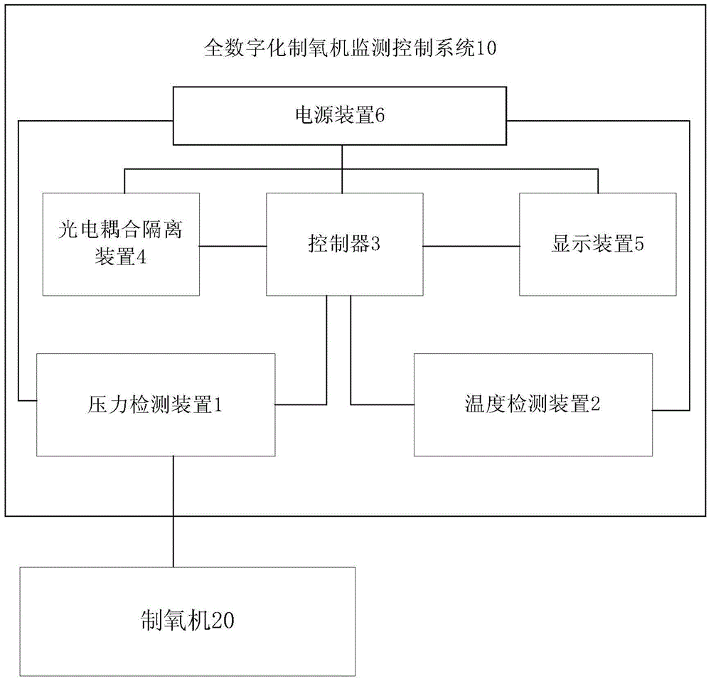
[0030] Such as figure 1 As shown, the fully digital oxygen generator monitoring and control system 10 provided by the embodiment of the present invention includes: a pressure detection device 1 , a temperature detection device 2 , a controller 3 , a photoelectric coupling isolation device 4 , a display device 5 and a power supply device 6 . The all-digital oxygen generator monitoring and control system 10 can be used for full-digital display, control and monitoring of the oxygen generator.

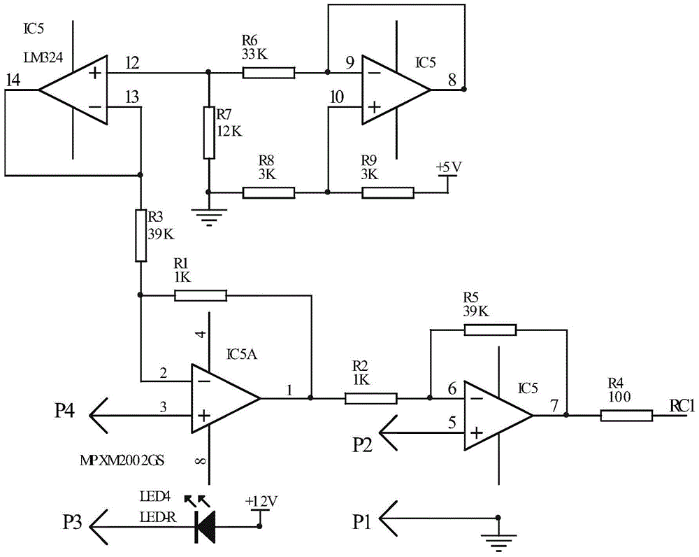
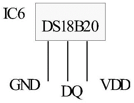
[0031] Specifically, the pressure dete...


PUM


Abstract

The invention provides a monitoring and controlling system of a full-digital oxygenerator. The monitoring and controlling system comprises a pressure detection device, a temperature detection device, a controller, a photocoupling isolating device, a display device and a power supply device. The pressure detection device is connected with the oxygenerator and used for detecting system pressure signals of the oxygenerator. A probe of the temperature detection device stretches into the oxygenerator, and the temperature detection device is used for detecting internal operating temperature signals of the oxygenerator. The controller is connected with the pressure detection device and the temperature detection device and used for setting a time interrupt source and an AD interrupt source. The photocoupling isolating device is connected with the controller and used for carrying out photocoupling isolation on the controller and an external circuit. The display device is connected with the controller and used for displaying pressure data, temperature data and time data after data algorithm processing. Digital control is adopted in the system, and production efficiency is improved.

Description

technical field [0001] The invention relates to the technical field of oxygen generator equipment, in particular to an all-digital oxygen generator monitoring and control system. Background technique [0002] The medical molecular sieve oxygen generator uses zeolite molecular sieve as the adsorbent, uses pressure swing adsorption (Pressure SwingAdsorption, PSA) to use air as the raw material at room temperature and low pressure, and directly separates the oxygen in the air (about 21%) by physical methods. , so as to produce high-purity medical oxygen with a concentration of 90% to 96%, which is characterized by fast oxygen production, safety, economy, convenience, and easy replacement of bottled oxygen and chemical oxygen production in the past, and has been widely used. While ensuring the safe and effective operation of the oxygen generator, the rapid oxygen output and the basic functions of medical standards, each oxygen generator manufacturer also continuously updates its...

Claims


Application Information

Patent Timeline
Patent Type & Authority Patents(China)
IPC IPC(8): G05B19/048
Inventor 孙保安石宝珠史磊
Owner 保定迈卓医疗器械有限公司
Why Eureka
Try Eureka