

Switch power source remote control circuit
A switching power supply and remote control circuit technology, applied in the direction of electrical components, output power conversion devices, etc., can solve the problems of poor anti-static interference, easy failure of undervoltage protection, flat temperature drift, etc., to improve overall performance and save layout The effect of less board space and less components
- Summary
- Abstract
- Description
- Claims
- Application Information
AI Technical Summary
Problems solved by technology
Method used
Image

Examples
Embodiment 1
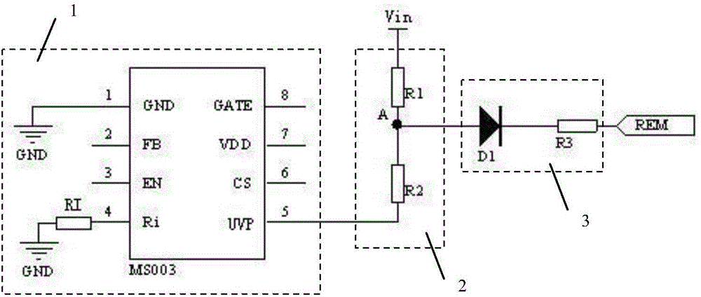
[0030] Such as figure 2Shown is a circuit diagram of Embodiment 1 of the present invention, including a switching power supply control circuit 1 , a voltage sampling circuit 2 and a remote control port circuit 3 . The switching power supply control circuit 1 can preferably be composed of a control chip IC MS003 and a resistor RI, the resistor RI is connected between the Ri terminal of the control IC MS003 and the ground, the voltage sampling circuit 2 is composed of resistors R1 and R2 connected in series, and the other end of the resistor R1 is connected The sampling voltage input terminal Vin, the other end of the resistor R2 is connected to the undervoltage protection terminal UVP of the control IC, the connection point of the two resistors is the second input terminal of the voltage sampling circuit 2, and the remote control pin REM is the input terminal of the remote control port circuit 3. The input terminal of the remote control port circuit 3 is connected to the secon...
Embodiment 2
[0043] In high and low temperature environments, the PN junction voltage drop of semiconductor devices will have obvious differences, generally 0.1-0.2V. Such differences will be continuously amplified with the design of the circuit, so that the remote control level will appear significantly in different environments. The difference between them will cause inconsistent remote control levels in high and low temperature environments. exist figure 2 The shown voltage sampling circuit 2 is added with Zener diode DZ1, such as Figure 4 In the second embodiment of the present invention shown, the cathode of the Zener diode DZ1 is connected to the voltage input terminal Vin, the anode is connected to the resistor R1, and the rest are connected with figure 2 The first embodiment shown is the same, because the conduction voltage drop of the semiconductor device will increase with the decrease of temperature, that is, Vbe will increase, so the voltage VI of the undervoltage protectio...
Embodiment 3
[0045] When there is a greater level of static electricity or a surge signal entering the circuit, it can be figure 2 The shown remote control port circuit 3 is added with a capacitor C1 with filter absorption function, such as Figure 5 In the third embodiment of the present invention shown, the capacitor C1 is connected between the remote control pin REM and the ground, and the rest are connected with the ground. figure 2 The embodiment 1 shown is the same, after the input terminal of the remote control port circuit 3, that is, the remote control pin REM increases the absorbing capacitor C1, it can absorb and bypass the instantaneous static pulse or surge signal to a certain extent, thereby improving the remote control pin REM. REM's anti-static rating.
PUM
 Abstract
Description
Claims
Application Information