Double-bootstrap three-level Zeta converter
A three-level, converter technology, applied in the direction of adjusting electrical variables, converting DC power input to DC power output, instruments, etc., can solve the problems of high loss, large equipment volume, and high cost, and achieve volume reduction and transformer reduction Equipment, cost saving effect
- Summary
- Abstract
- Description
- Claims
- Application Information
AI Technical Summary
Problems solved by technology
Method used
Image
Examples
specific Embodiment approach 1
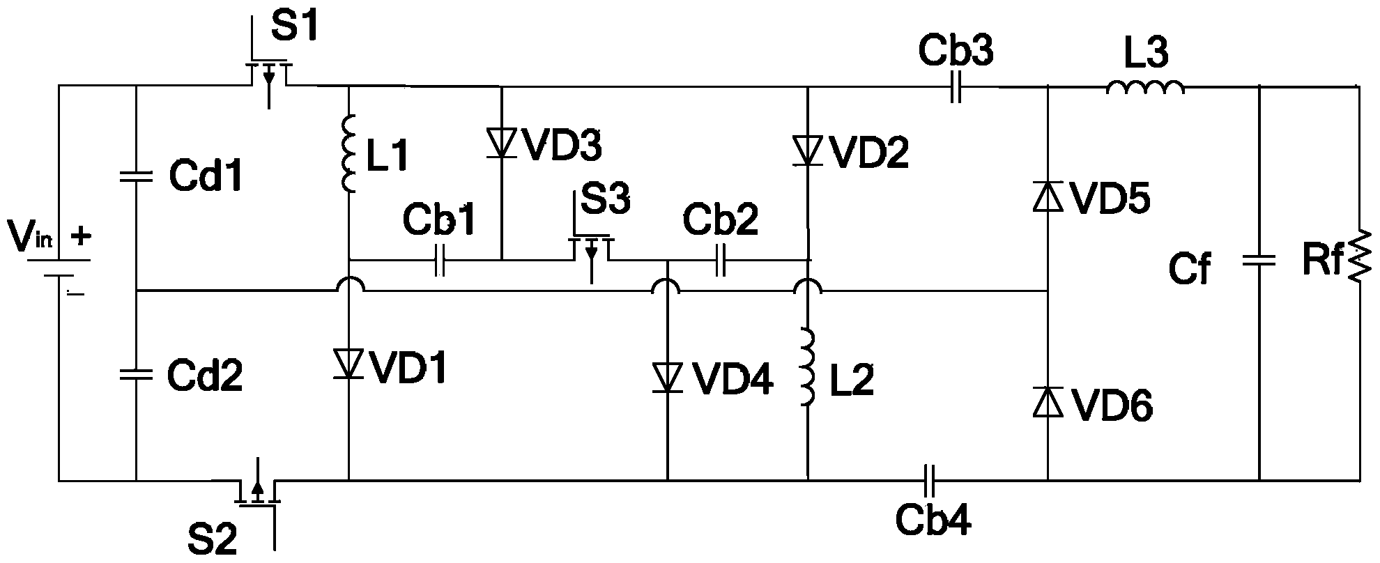
[0025] Specific implementation mode one: refer to figure 1 Describe this embodiment in detail, the dual-bootstrap three-level Zeta converter described in this embodiment includes: power supply Vin, capacitor Cd1 of No. 1, capacitor Cd2 of No. 2, capacitor Cb1 of No. 3, capacitor Cb2 of No. 4, capacitor No. 5 Capacitor Cb3, No. 6 capacitor Cb4, No. 7 capacitor Cf, No. 1 switch tube S1, No. 2 switch tube S2, No. 3 switch tube S3, No. 1 inductor L1, No. 2 inductor L2, No. 3 inductor L3, resistor Rf, a No. diode VD1, No. 2 diode VD2, No. 3 diode VD3, No. 4 diode VD4, No. 5 diode VD5 and No. 6 diode VD6;
[0026] The positive pole of the power supply Vin is simultaneously connected to one end of the first capacitor Cd1 and the source of the first switch tube S1,
[0027] The drain of the No. 1 switch tube S1 is simultaneously connected to one end of the No. 1 inductor L1, the anode of the No. 3 diode VD3, the anode of the No. 2 diode VD2, and one end of the No. 5 capacitor Cb3.
...
specific Embodiment approach 2
[0076] Embodiment 2: This embodiment is a further description of the dual-bootstrap three-level Zeta converter described in Embodiment 1. In this embodiment, the voltage of the power supply Vin is 10V.
specific Embodiment approach 3
[0077] Specific embodiment three: this embodiment is a further description of the dual-bootstrap three-level Zeta converter described in specific embodiment two. In this embodiment, the driving signals of the first switching tube S1 and the second switching tube S2 The frequency is 50kHz and the duty cycle is 0.7.
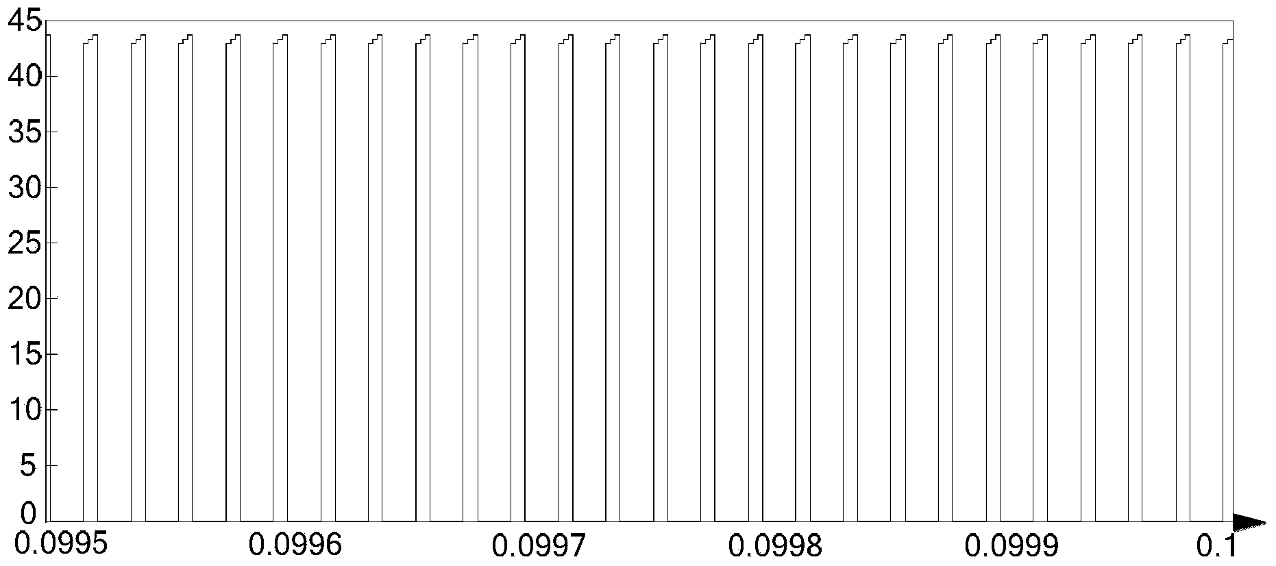
[0078] This specific implementation is studied by means of simulation. In the simulation process, the input voltage is selected to be 10V, the frequencies of the first switch tube S1 and the second switch tube S2 are both 50kHz, and the duty cycle is 0.7. The first switch tube S1, The second switching tube S2 and the third switching tube S3 realize complementary conduction. The voltage waveform at both ends of switch tube S1 is as follows: image 3 As shown, the voltage waveforms at both ends of the fifth diode VD5 and the sixth diode VD6 are as follows Figure 4 As shown, the converter output voltage waveform is as Figure 5 shown.
[0079] From image 3 , ...
PUM
 Abstract
Description
Claims
Application Information
 - R&D
- Intellectual Property
- Life Sciences
- Materials
- Tech Scout
- Unparalleled Data Quality
- Higher Quality Content
- 60% Fewer Hallucinations
Browse by: Latest US Patents, China's latest patents, Technical Efficacy Thesaurus, Application Domain, Technology Topic, Popular Technical Reports.
© 2025 PatSnap. All rights reserved.Legal|Privacy policy|Modern Slavery Act Transparency Statement|Sitemap|About US| Contact US: help@patsnap.com


