
Single-stage type high-conversion-ratio Buck-Boost inverter

A high conversion and inverter technology, applied in the direction of output power conversion device, AC power input conversion to DC power output, electrical components, etc., can solve the problem of weakening flyback topology, simple structure, reduced decoupling capacitor, efficiency Lowering and other issues

Inactive Publication Date: 2017-12-22
NORTHWESTERN POLYTECHNICAL UNIV
View PDF2 Cites 0 Cited by
  • Summary
  • Abstract
  • Description
  • Claims
  • Application Information

AI Technical Summary

Problems solved by technology

[0003] In the solution adopted by the single-stage high conversion ratio inverter, the flyback topology can have a high conversion ratio due to the use of a transformer. However, due to its single-stage structure, a decoupling circuit has to be added to reduce the solution. Coupling capacitors, which will weaken the simple characteristics of the flyback topology, increase the number of devices, and reduce efficiency; Boost topology has a high-voltage bus that makes power decoupling easier, but the topologies that have been found in the literature are all restricted Due to the disadvantage of limited conversion ratio; most of the Buck-Boost topology is still limited by the limited voltage conversion ratio, and some topologies can achieve high conversion ratio, but the number of devices is greatly increased

Method used


Image

  • Single-stage type high-conversion-ratio Buck-Boost inverter
  • Single-stage type high-conversion-ratio Buck-Boost inverter
  • Single-stage type high-conversion-ratio Buck-Boost inverter

Examples


Embodiment Construction

[0026] Now in conjunction with embodiment, accompanying drawing, the present invention will be further described:

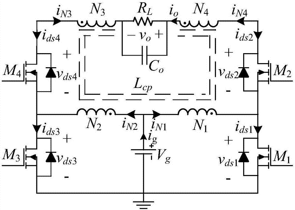
[0027] Such as figure 1 As shown, the topology basic structure of the present invention is a common full-bridge circuit, and the switching tubes are respectively M 1 ~ M 4 . Coupled inductor N 1 :N 2 :N 3 :N 4 Used as an energy storage device to achieve a high conversion ratio boost, the secondary to primary turns ratio is defined as n=N 4 / N 1 =N 3 / N 2 . Due to the symmetry of the positive and negative half cycles of the output, the primary winding N 1 with N 2 have the same number of turns, therefore, the secondary winding N 3 with N 4 also have the same number of turns. The output capacitor is C o , the load is the equivalent resistance R L .

[0028] Among them, the switching tube M 1 , M 3 The source and the negative pole of the input power supply are connected and grounded, and the switching tube M 1 The drain, M 2 source of the coupl...


PUM


Abstract

The invention relates to a single-stage type high-conversion-ratio Buck-Boost inverter. The single-stage type high-conversion-ratio Buck-Boost inverter comprises a full bridge circuit consisting of four switching tubes (M1-M4), a coupling inductor Lcp having four windings, an output filtering capacitor Co and an equivalent load Rl. The coupling inductor is designed as two pairs of symmetric windings. The primary-end winding of the coupling inductor has same windings N1=N2 and the auxiliary side of the coupling inductor has same windings N3=N4. The transformation ratio of the coupling inductor is n=N3 / N1=N4 / N2. Targeting a problem that most of topologies of the Buck-Boost type single-stage type inverter are limited by limited voltage transformation ratios and although few topologies can realize high transformation ratios, the quantity of devices is greatly increased, the invention provides a single-stage high-transformation ratio Buck-Boost inverter topology, which can realize a high transformation ratio under a condition that semiconductor devices are few.

Description

technical field [0001] The invention belongs to the field of power electronics and relates to a single-stage Buck-Boost inverter with high conversion ratio. Background technique [0002] In the field of renewable energy such as photovoltaics and fuel cells, inverters with high conversion ratios are essential. Due to the ease of control and implementation, usually, a two-stage inverter is used. However, due to lower cost and higher efficiency, single-stage inverters have attracted widespread interest from scholars. Looking at the literature published so far, it mainly involves the types of flyback, Boost, and Buck-Boost. [0003] In the solution adopted by the single-stage high conversion ratio inverter, the flyback topology can have a high conversion ratio due to the use of a transformer. However, due to its single-stage structure, a decoupling circuit has to be added to reduce the solution. Coupling capacitors, which will weaken the simple characteristics of the flyback ...

Claims


Application Information

Patent Timeline
IPC IPC(8): H02M7/5387
CPCH02M7/5387
Inventor 赵犇相里康皇甫宜耿马瑞卿
Owner NORTHWESTERN POLYTECHNICAL UNIV
Learn More