Output control method and device for physical factors

A technology of output control and factor, which is applied in the field of medical applications, can solve the problems of tissue damage, affect the treatment effect, produce tolerance, etc., and achieve the effect of improving the effect

Active Publication Date: 2014-08-13
JIANLIPU BEIJING MEDICAL TECH
View PDF5 Cites 3 Cited by
  • Summary
  • Abstract
  • Description
  • Claims
  • Application Information

AI Technical Summary

Problems solved by technology

[0003] However, in actual treatment, since the output of the light source generator is a continuous light signal or an intermittent light signal, its power is constant, that is to say, the light energy irradiated to the diseased part of the patient The intensity is fixed. Therefore, after multiple treatme

Method used


Image

  • Output control method and device for physical factors
  • Output control method and device for physical factors
  • Output control method and device for physical factors

Examples


Example Embodiment

[0051] Embodiment one:

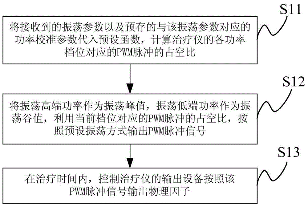
[0052] like figure 1 Shown is a flow chart of a physical factor output control method of the present invention, the method is applied to a therapeutic instrument, and the specific steps of the method may include:

[0053] Step S11: According to the received oscillation parameters and the pre-stored power calibration parameters corresponding to the oscillation parameters, calculate the duty cycle of the PWM pulse corresponding to each power level of the therapeutic apparatus.

[0054] Wherein, the above-mentioned oscillation parameters may include: oscillation high-end power, oscillation low-end power and treatment time, etc., and the oscillation high-end power is greater than the oscillation low-end power and not greater than the rated maximum power, and the oscillation low-end power is not less than zero.

[0055] In the embodiment of the present invention, the operator can first determine which physical factor is suitable for treatment according to ...

Example Embodiment

[0096] Embodiment two:

[0097] like Figure 4 As shown, the embodiment of the present invention provides a schematic structural diagram of a physical factor output control device. The control device is applied to a therapeutic instrument, and may specifically include: sequentially connected input device S41, controller S42, power supply control circuit S43, and output device S44, of which,

[0098] Input device S41: for receiving the oscillation parameters input by the operator.

[0099] In the embodiment of the present invention, the oscillation parameters may include oscillation high-end power, oscillation low-end power, and treatment time, and the oscillation high-end power is greater than the oscillation low-end power and not greater than the rated maximum power, and the oscillation low-end power is not less than zero. In practical applications, the input device may specifically be a keypad (ie, a keyboard), on which keys corresponding to different operations are arrang...


PUM


Abstract

The invention provides an output control method and device for physical factors. The output control method includes the steps of substituting received oscillation parameters and pre-stored power calibration parameters corresponding to the oscillation parameters into a preset function, and calculating duty ratios of PWM pulses corresponding to power gears of a therapeutic apparatus; enabling the oscillation high-end power to serve as the oscillation peak value and the oscillation low-end power to serve as the oscillation valley value, and outputting PWM pulse signals according to a preset oscillation mode with the duty ratio of the PWM pulse corresponding to the current power gear so that a power control circuit can control an output device in a set therapy time to output the physical factors according to the PWM pulse signals. Due to the fact that the power is continuously changed within any interval between zero and the rated maximum power, the biological tissues of a patient are prevented from generating tolerance caused by constant energy of the physical factors, the human body tissues of the patient are prevented from being damaged by excessively-large energy of the physical factors, the requirements of illness states of different bodies and in different stages for the energy of the physical factors are met, and the therapy adjuvant effect of the therapeutic apparatus is improved.

Description

technical field [0001] The invention relates to the field of medical applications, and more specifically relates to a method and device for controlling the output of physical factors. Background technique [0002] At present, with the rapid development of the medical level, it has become the mainstream in this field to use various therapeutic instruments to assist in the treatment of some diseases. , so that it can generate light signals with fixed energy intensity, and irradiate relevant parts of the patient to assist in the treatment of acute and chronic diseases, neuropathic pain and dysfunction, such as acute and chronic injuries of the motor system, rheumatism, infection and non-infectious inflammation And skin diseases, etc., greatly shortening the treatment time of patients and reducing the pain of patients. [0003] However, in actual treatment, since the output of the light source generator is a continuous light signal or an intermittent light signal, its power is ...

Claims


Application Information

Patent Timeline
IPC IPC(8): H03K5/156H03K7/08
Inventor 张志标
Owner JIANLIPU BEIJING MEDICAL TECH
Why Eureka
Try Eureka