Method for manufacturing brake disc, support bell for brake disc and brake disc

A bell-shaped, brake band technology, applied in the direction of brake components, brake discs, brake types, etc., to solve problems such as increasing storage and transportation volume and weight

Active Publication Date: 2017-03-08
PETROCERAMICS
View PDF1 Cites 0 Cited by
  • Summary
  • Abstract
  • Description
  • Claims
  • Application Information

AI Technical Summary

Problems solved by technology

However, this solution involves undesired costs for installing and removing the s

Method used


Image

  • Method for manufacturing brake disc, support bell for brake disc and brake disc
  • Method for manufacturing brake disc, support bell for brake disc and brake disc
  • Method for manufacturing brake disc, support bell for brake disc and brake disc

Examples


Embodiment Construction

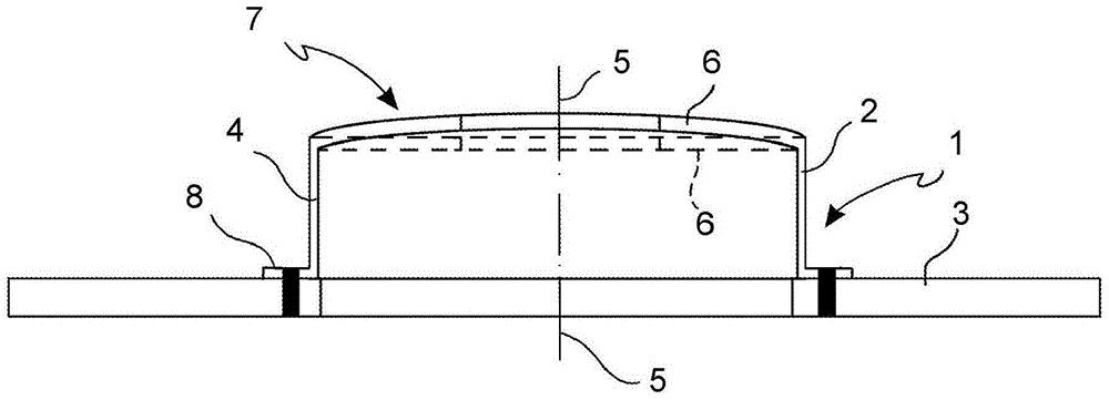
[0046] With reference to the accompanying drawings, a composite brake disc is fully indicated with reference numeral 1 and comprises a bell 2 made of a first material, preferably sheet metal, in particular steel or aluminum alloy, and comprises Brake band 3 made of a second material, eg cast iron, aluminum alloy or fiber reinforced ceramic material.

[0047] The bell 2 has a connection 7 for connecting the brake disc 1 to the hub of the vehicle and a coupling 8 for connecting the bell 2 to the brake band 3 . The connecting portion 7 of the bell 2 is shaped as a cup having a tubular side wall 4 substantially coaxial with the axis of rotation (generally the axis of symmetry) 5 of the brake disc 1 and having transverse to the side wall 4 and preferably The bottom wall 6 is substantially perpendicular to the axis of rotation 5 . A coupling portion 8 is generally formed at the end of the side wall 4 opposite to the bottom wall 6 .

[0048] Brake band 3 ( Figure 3A to Figure 3C ...


PUM


Abstract

A method for manufacturing a composite brake disc (1), the method comprising shaping a bell (2) by deep drawing of a metal sheet (20); in the surface of the bottom (24) of the metal sheet (20) forming at least one groove (22) and then pushing the base (24) relative to the outer portion (25) in a counter-forming direction (23) opposite to the stretching direction (20); attaching the brake band (3) to the bell shape (2).

Description

technical field [0001] The object of the invention is a method for producing a composite brake disc of a motor vehicle, in other words a method for producing a brake disc, a brake band and a support bell made of different materials. Support bells for composite discs as well as composite brake discs also form the object of the invention. Background technique [0002] Composite brake discs are generally known, for example from US2007 / 284200A1. Since the brake band is separated from the supporting bell, composite brake discs may optimize the components both in terms of methods and materials to obtain each component for a specific application (mechanical, thermal and frictional). Thus, for example, it is possible to combine a brake band made of cast iron with good friction and thermal conductivity properties with a support bell made of steel sheet with high mechanical strength and low weight. [0003] The prior art support bell has a coupling portion adapted to connect the bel...

Claims


Application Information

Patent Timeline
IPC IPC(8): F16D65/12B21D22/20
CPCB21D22/20B21D53/88F16D65/12F16D2065/1316F16D2250/0023Y10T29/49826
Inventor 马西米利亚诺·瓦莱
Owner PETROCERAMICS
Why Eureka
Try Eureka