Pipeline organ cast forming device and use method thereof

A technology of pouring molding and organs, which is applied in the field of biomedicine, can solve the problems of few patents, achieve the effect of simple disassembly and assembly, overcome the limitations of raw materials and the control of pipeline shape and structure, and the effect of easy demoulding

Inactive Publication Date: 2014-08-20
DONGHUA UNIV
View PDF9 Cites 3 Cited by
  • Summary
  • Abstract
  • Description
  • Claims
  • Application Information

AI Technical Summary

Problems solved by technology

[0003] At present, there are few patents on the pouring molding device for medical pipeline organs at home and abroad

Method used


Image

  • Pipeline organ cast forming device and use method thereof
  • Pipeline organ cast forming device and use method thereof
  • Pipeline organ cast forming device and use method thereof

Examples


Embodiment 1

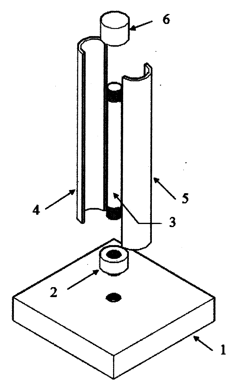
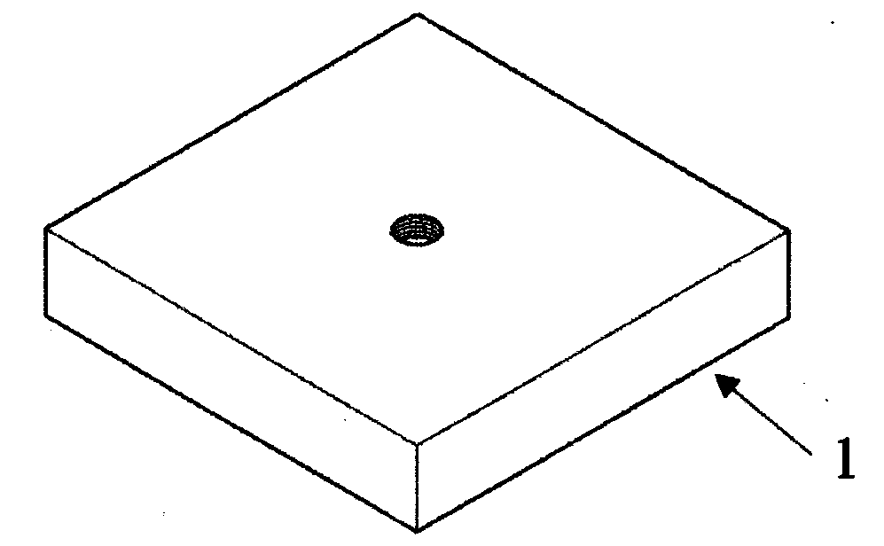
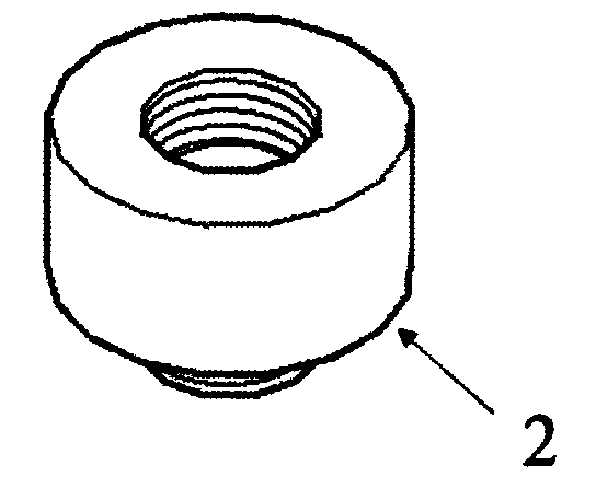
[0028] Such as figure 1 As shown, it is a schematic structural diagram of the pouring and molding device for pipe organs of the present invention. The device for pouring and molding pipe organs includes a base 1, a lower fixing cap 2, a stem 3, a casing one 4, a casing two 5, an upper fixing cap 6 and a tubular Shell, the lower fixing cap 2 is connected with the base 1 through threads, one end of the stem 3 is connected with the lower fixing cap 2 through threads, the upper fixing cap 6 is connected with the other end of the stem 3 through threads, and the tubular shell is surrounded by the upper fixing cap 6 and the lower On the outside of the fixed cap 2, a cavity is formed between the tubular shell and the stem 3. The tubular shell is composed of a shell one 4 and a shell two 5. The sides of the shell one 4 and the shell two 5 are connected in a detachable manner. The detachable method described above is a concave-convex matching method.

[0029] Such as figure 2 As show...

Embodiment 2

[0035] Such as figure 1 As shown, it is a schematic structural diagram of the pouring and molding device for pipe organs of the present invention. The device for pouring and molding pipe organs includes a base 1, a lower fixing cap 2, a stem 3, a casing one 4, a casing two 5, an upper fixing cap 6 and a tubular Shell, the lower fixing cap 2 is connected with the base 1 through threads, one end of the stem 3 is connected with the lower fixing cap 2 through threads, the upper fixing cap 6 is connected with the other end of the stem 3 through threads, and the tubular shell is surrounded by the upper fixing cap 6 and the lower On the outside of the fixed cap 2, a cavity is formed between the tubular shell and the stem 3. The tubular shell is composed of a shell one 4 and a shell two 5. The sides of the shell one 4 and the shell two 5 are connected in a detachable manner. The detachable method described above is a concave-convex matching method.

[0036] Such as figure 2 As show...

Embodiment 3

[0042] Such as figure 1 As shown, it is a schematic structural diagram of the pouring and molding device for pipe organs of the present invention. The device for pouring and molding pipe organs includes a base 1, a lower fixing cap 2, a stem 3, a casing one 4, a casing two 5, an upper fixing cap 6 and a tubular Shell, the lower fixing cap 2 is connected with the base 1 through threads, one end of the stem 3 is connected with the lower fixing cap 2 through threads, the upper fixing cap 6 is connected with the other end of the stem 3 through threads, and the tubular shell is surrounded by the upper fixing cap 6 and the lower On the outside of the fixed cap 2, a cavity is formed between the tubular shell and the stem 3. The tubular shell is composed of a shell one 4 and a shell two 5. The sides of the shell one 4 and the shell two 5 are connected in a detachable manner. The detachable method described above is a concave-convex matching method.

[0043] Such as figure 2 As show...


PUM


Abstract

The invention provides a pipeline organ cast forming device and a use method thereof. The pipeline organ cast forming device is characterized by comprising a base, a lower fixing nut, a core column, a first shell, a second shell, an upper fixing nut and a tubular shell, the lower fixing nut is connected with the base through threads, one end of the core column is connected with the lower fixing nut through threads, the upper fixing nut is connected with the other end of the core column through threads, the tubular shell surrounds the upper fixing nut and the lower fixing nut, a cavity is formed between the tubular shell and the core column, the tubular shell is composed of the first shell and the second shell, and the lateral side of the first shell and the lateral side of the second shell are connected in a detachable mode, namely, a concave-convex matching mode. By means of the pipeline organ cast forming device, a seamless pipeline with the accurate and controllable inner diameter and the accurate and controllable outer diameter can be formed at a time; the pipeline organ cast forming device is easy to detach and assemble and can be demoulded easily. The pipeline organ cast forming device is suitable for forming pipeline organs by casting polymer solutions.

Description

technical field [0001] The invention relates to a pouring molding device for pipe organs and a method for using the same, belonging to the technical field of biomedicine. Background technique [0002] The pipeline structure has a wide range of applications in the field of biomedical materials, such as artificial blood vessels, artificial esophagus, ureteral stents, etc. At present, biomedical pipeline materials mainly include polyester filament, silk fiber, ePTFE and other natural or synthetic degradable or non-degradable polymer materials. The forming methods include weaving, weaving, knitting, injection molding and electrospinning. Pipes with different shapes, structures and properties can be obtained by using different combinations of materials and molding methods. [0003] At present, there are few patents on the pouring molding device for medical pipeline organs both at home and abroad. There is one patent similar to the present invention, the patent "An artificial b...

Claims


Application Information

Patent Timeline
Patent Type & Authority Applications(China)
IPC IPC(8): A61F2/04
Inventor 关国平沈高天王璐王富军胡星友徐睿黄健涛
Owner DONGHUA UNIV
Why Eureka
Try Eureka