Kneeling position static and dynamic balance training device
The technology of a training device and a reset device is applied in the directions of training equipment for adjusting coordination, training equipment for adjusting cardiovascular system, sports accessories, etc., which can solve the problems of single standing balance, little help, and inability to establish patient dynamic balance, etc. To achieve the effect of improving safety, reasonable design and convenient use
- Summary
- Abstract
- Description
- Claims
- Application Information
AI Technical Summary
Problems solved by technology
Method used
Image
Examples
Embodiment 1
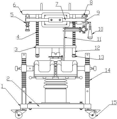
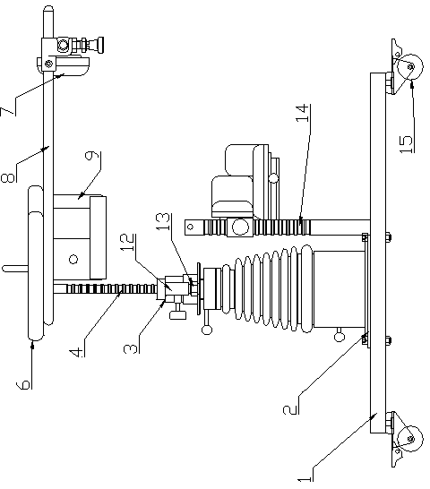
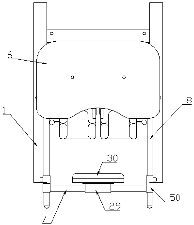
[0029] Embodiment 1, with reference to Figure 1-Figure 7 , a dynamic and static balance training device for kneeling and standing position, comprising a vehicle frame 1, and the vehicle frame 1 is provided with an underframe device and a panel device;
[0030] The underframe device includes an underframe 2 and an underframe reset device fixed thereon, and the panel device includes a panel frame 5 and a panel 6 fixed thereon, and a controller and a braking device are installed on the panel frame 5;
[0031] The controller includes an angle gyroscope and a single-chip microcomputer installed on the panel frame 5, and the braking device includes an angle brake 10 and a brake line 11. The angle brake 10 is fixed on the panel frame 5 by a connector 9, and one end of the brake line 11 is connected to the angle brake. 10 on;
[0032] On the underframe 2 in front of the underframe resetting device, two upwardly arranged knee assembly support slide bars 14 are symmetrically fixed, an...
Embodiment 2
[0035] Embodiment 2, with reference to Figure 8 , in the static and dynamic balance training device for kneeling position described in embodiment 1: the chassis reset device includes a support sleeve 48, a mandrel 42 and a universal joint 32, and the bottom of the support sleeve 48 is fixed on the bottom plate 2 of the vehicle frame 1 On, the bottom end of the universal joint 32 is fixed on the bottom plate 2 in the supporting sleeve 48, the upper end of the mandrel 42 is connected with the middle sliding sleeve fixing frame 3, and the lower end is connected with the universal joint 32, and the upper end of the universal joint 32 is set A limit sleeve 47 threaded with the universal joint is provided, and a limit transmission handle 33 protruding from the support sleeve 48 is connected on the limit sleeve 47. On the mandrel 42 above the limit sleeve 47 and below the support sleeve 48 Also be provided with bearing 34 and limit block 46, limit block 46 is located at the below of...
Embodiment 3
[0036] Embodiment 3, in the static and dynamic balance training device for kneeling standing position described in Embodiment 1: the bottom of the knee sliding frame 18 is provided with an installation groove 27 with an opening downward, and a knee rotating frame 22 is hinged in the installation groove 27, The left and right groove walls of the knee swivel frame 22 and the installation groove 27 are provided with positioning pull pins 28, and the top of the knee swivel frame 22 is provided with a positioning chute vertically arranged with the knee cross bar 19, and the top of the positioning chute is provided with a positioning chute. Protective pad fixed plate 24 and the protective pad fixed on it are arranged, the protective pad fixed plate 24 is provided with the positioning slide block 23 that cooperates with the positioning chute, is provided with the positioning hole 25 on the positioning chute and the positioning slide block 23, the positioning The positioning shaft 21 c...
PUM
 Abstract
Description
Claims
Application Information
 - R&D
- Intellectual Property
- Life Sciences
- Materials
- Tech Scout
- Unparalleled Data Quality
- Higher Quality Content
- 60% Fewer Hallucinations
Browse by: Latest US Patents, China's latest patents, Technical Efficacy Thesaurus, Application Domain, Technology Topic, Popular Technical Reports.
© 2025 PatSnap. All rights reserved.Legal|Privacy policy|Modern Slavery Act Transparency Statement|Sitemap|About US| Contact US: help@patsnap.com


