Transmission type hydraulic pump with crank connecting rod structure

A crank connecting rod and transmission technology, applied in the field of machinery, can solve the problems of asymmetric overall layout of double-acting piston pumps, high price of servo variable axial piston pumps, high manufacturing costs, etc., and achieve compact structure, The effect of large output force and balanced force

Inactive Publication Date: 2014-08-20
SUZHOU POLYTECHNIC INST OF AGRI
View PDF8 Cites 3 Cited by
  • Summary
  • Abstract
  • Description
  • Claims
  • Application Information

AI Technical Summary

Problems solved by technology

Therefore, an excessive number of plungers is actually a helpless choice, which not only makes the mechanism complicated, but also makes the manufacturing cost high
[0003] The hydraulic drive system of a hydraulic elevator is a typical hydraulic system that requires continuous speed regulation. In terms of energy saving and operating costs, it is ideal to use a servo variable axial piston pump for speed regulation. However, a servo variable axial piston pump The extremely expensive price and high failure rate limit its application in hydraulic elevators
[0004] The Chinese patent with the authorized notification number CN 102207066 B also discloses a double-acting plunger pump driven by a symmetrical toggle lever, but this double-acting plunger pump only shows the last stage of mechanical transmission. With the driving motor, you will find that the overall layout of the double-acting plunger pump is extremely asymmetrical
In addition, the toggle mechanism in the double-acting plunger pump is hinged on the eccentric pin shaft on the end face of the gear. The pin shaft is a cantilever beam, and the stress condition is extremely poor.

Method used


Image

  • Transmission type hydraulic pump with crank connecting rod structure

Examples


Embodiment Construction

[0019] Specific embodiments of the present invention will be further described in detail below.

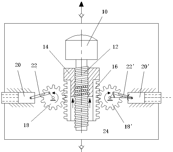
[0020] as attached figure 1 As shown, the transmission hydraulic pump adopting the crank connecting rod structure of the present invention includes a motor 10 . The output shaft of the motor 10 is fixedly connected with a lead screw 12 , and a nut 14 is cooperatingly arranged on the lead screw 12 . A two-sided rack 16 is fixedly connected to the nut 14, and a gear 18 and a gear 18' meshed with the rack 16 are respectively arranged on both sides. Of course, those of ordinary skill in the art can easily think of a rack 16 fixedly connected to the nut 14 according to the thinking of the present invention, and several gears 18 and gears 18' are arranged on the same side of the rack 16; or on both sides of the nut 14 Two separate racks 16 are arranged, and a plurality of gears 18 and gears 18 ′ are arranged along the direction of the racks 16 to realize the function of the hydraulic ...


PUM


Abstract

The invention discloses a transmission type hydraulic pump with a crank connecting rod structure. The transmission type hydraulic pump comprises at least one plunger piston which is movably arranged in a containing cavity. The transmission type hydraulic pump is characterized by further comprising a motor, an output shaft of the motor is coaxially connected with a lead screw, the lead screw is in threaded connection with a nut in a sleeved mode, at least one rack is fixedly connected to the nut in the length direction of the lead screw, a machine tool is provided with at least one gear meshed with the rack, the plunger piston is connected to the eccentric position of the gear through a hinged rod, and the hinged rod is hinged to the gear and the plunger piston. The transmission type hydraulic pump with the crank connecting rod structure has the advantages of being simple in structure, low in cost and capable of continuously adjusting flow and pressure.

Description

technical field [0001] The invention belongs to the mechanical field and relates to a transmission hydraulic pump adopting a crank connecting rod structure. Background technique [0002] At present, the throttling speed regulating system hydraulic speed regulating technology widely used in the industrial field mainly includes the throttling speed regulating system composed of a constant pump and a throttle valve and the pump speed regulating system driven by a variable pump. High-power hydraulic pumps with continuously adjustable flow and pressure are mainly swash plate axial piston pumps, but the structure of the swash plate axial piston pump is extremely complicated, especially the plunger has to withstand the radial force formed Torque, which makes its friction conditions deteriorate, service life and mechanical efficiency are reduced. In addition, the sliding shoe connected to the lower end of the plunger has a complex structure, extremely harsh friction conditions, and...

Claims


Application Information

Patent Timeline
Patent Type & Authority Applications(China)
IPC IPC(8): F04B17/03
Inventor 吴凡秦培亮夏春风钟康民
Owner SUZHOU POLYTECHNIC INST OF AGRI
Why Eureka
Try Eureka