Eureka AIR delivers breakthrough ideas for toughest innovation challenges, trusted by R&D personnel around the world.

Flue gas heating treatment device

A technology for processing equipment and flue gas heating, which is applied in the field of flue gas treatment, can solve the problems of corrosion, damage and economic loss of flue gas heating treatment equipment, and achieve the effects of improving flue gas heating efficiency, compact structure, and long service life

Active Publication Date: 2014-08-20
ZHEJIANG ERG TECH
View PDF11 Cites 1 Cited by
  • Summary
  • Abstract
  • Description
  • Claims
  • Application Information

AI Technical Summary

Problems solved by technology

[0005] The object of the present invention is to solve the above-mentioned problems in the prior art, and provide flue gas heating treatment equipment, which is easy to install and maintain, and solves the problem of large economic losses caused by corrosion and damage of flue gas heating treatment equipment

Method used


Image

  • Flue gas heating treatment device
  • Flue gas heating treatment device
  • Flue gas heating treatment device

Examples


Embodiment Construction

[0024] The following are specific embodiments of the present invention and in conjunction with the accompanying drawings, the technical solutions of the present invention are further described, but the present invention is not limited to these embodiments.

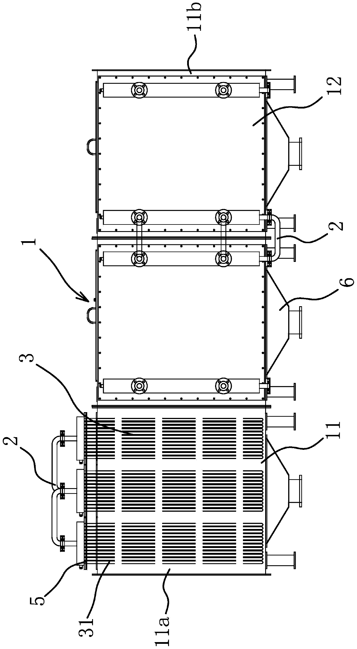
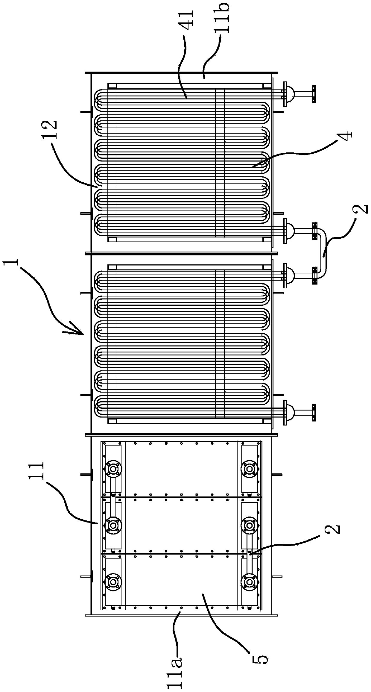
[0025] Such as figure 1 , figure 2 As shown, the flue gas heating treatment equipment includes a flue gas duct 1 , a steam pipe 2 , a drawer core 3 , a fixed core 4 , a fixed plate 5 and an inverted tapered bucket 6 .

[0026] The flue gas duct 1 includes a first air duct 11 and a fixed air duct 12. In this embodiment, the number of the fixed air ducts 12 is two, and may be one or three in actual production. Both the first air cylinder 11 and the fixed air cylinder 12 are in the shape of a cube. The width of the first air cylinder 11 and the fixed air cylinder 12 along the flue gas flow direction of the flue gas duct 1 is the same. The first air cylinder 11 and the two fixed air cylinders 12 are fixedly connected in ser...


PUM


Abstract

The invention provides a flue gas heating treatment device, and belongs to the technical field of flue gas treatment. The device solves the problem that after an existing flue gas heating treatment device is corroded and damaged, economic losses are large. The device comprises a flue gas air channel and a plurality of steam pipelines, a plurality of drawer type core bodies which are composed of first heat exchange pipes and can be drawn out are arranged in the flue gas air channel, a plurality of fixed core bodies composed of second heat exchange pipes are fixedly connected in the flue gas air channel, the drawer type core bodies are arranged at the air inlet ends of the flue gas air channel, the drawer type core bodies are communicated with the steam pipelines, the fixed core bodies are arranged at the middle segment and the air outlet end of the flue gas air channel, and the fixed core bodies are communicated with the steam pipelines. The flue gas heating treatment device has the advantages of being convenient to mount and maintain, improving flue gas heating efficiency and the like.

Description

technical field [0001] The invention belongs to the technical field of flue gas treatment, and relates to flue gas heating treatment equipment, in particular to flue gas heating treatment equipment applied to energy saving and environmental protection. Background technique [0002] Domestic waste incineration and hazardous waste incineration will produce a large amount of flue gas, which not only contains a large amount of acid gas (mainly HCL, SO2), dust particles, heavy metals, dioxins and other pollutants produced after incineration, but also contains a large amount of water vapor . At present, for the flue gas discharged into the atmosphere, the acid gas will be deacidified, and the dust particles and heavy metals will be dedusted and adsorbed, and will be discharged into the atmosphere after reaching the clean gas emission standard. [0003] However, after wet deacidification, the flue gas is discharged from the chimney in a saturated state. When the ambient temperatur...

Claims


Application Information

Patent Timeline
Patent Type & Authority Applications(China)
IPC IPC(8): F23J15/08
Inventor 虞礼辉黎贤钛洪方龙杨性晓王汪洋
Owner ZHEJIANG ERG TECH
Why Eureka
Eureka Blog
Learn More