Head mounted display and control method for head mounted display

A display device, wearable technology, applied to static indicators, cathode ray tube indicators, and equipment for radiological diagnosis, etc., can solve the problem of not being able to directly see the surgical site

Active Publication Date: 2014-08-20
SEIKO EPSON CORP
View PDF9 Cites 25 Cited by
  • Summary
  • Abstract
  • Description
  • Claims
  • Application Information

AI Technical Summary

Problems solved by technology

However, in the technique described in Patent Document 1, there is a problem that the user of the head-mounted display device cannot directly see the surgical site (patient's body)
In addition, in the technology described in Patent Document 2, there is a problem that the user of the head-mounted display needs to move the line of sight in the vertical direction in order to directly see the surgical site.
[0007] In addition, such problems do not only exist in endoscopic images, for example, when CT (Computed Tomography, computerized tomography) images, MRI (Magnetic Resonance Imaging, magnetic resonance imaging) images, X-ray images, etc. do not appear on the object Problems common to situations where information on the appearance of a head-mounted display is provided to the user
Moreover, such problems exist not only in medical head-mounted display devices, but also in head-mounted display devices used in other applications (for example, in construction sites, to provide users with The same problem exists in the head-mounted display device of the information in the appearance)

Method used


Image

  • Head mounted display and control method for head mounted display
  • Head mounted display and control method for head mounted display
  • Head mounted display and control method for head mounted display

Examples


no. 1 Embodiment approach

[0065] A-1. Composition of the head-mounted display device:

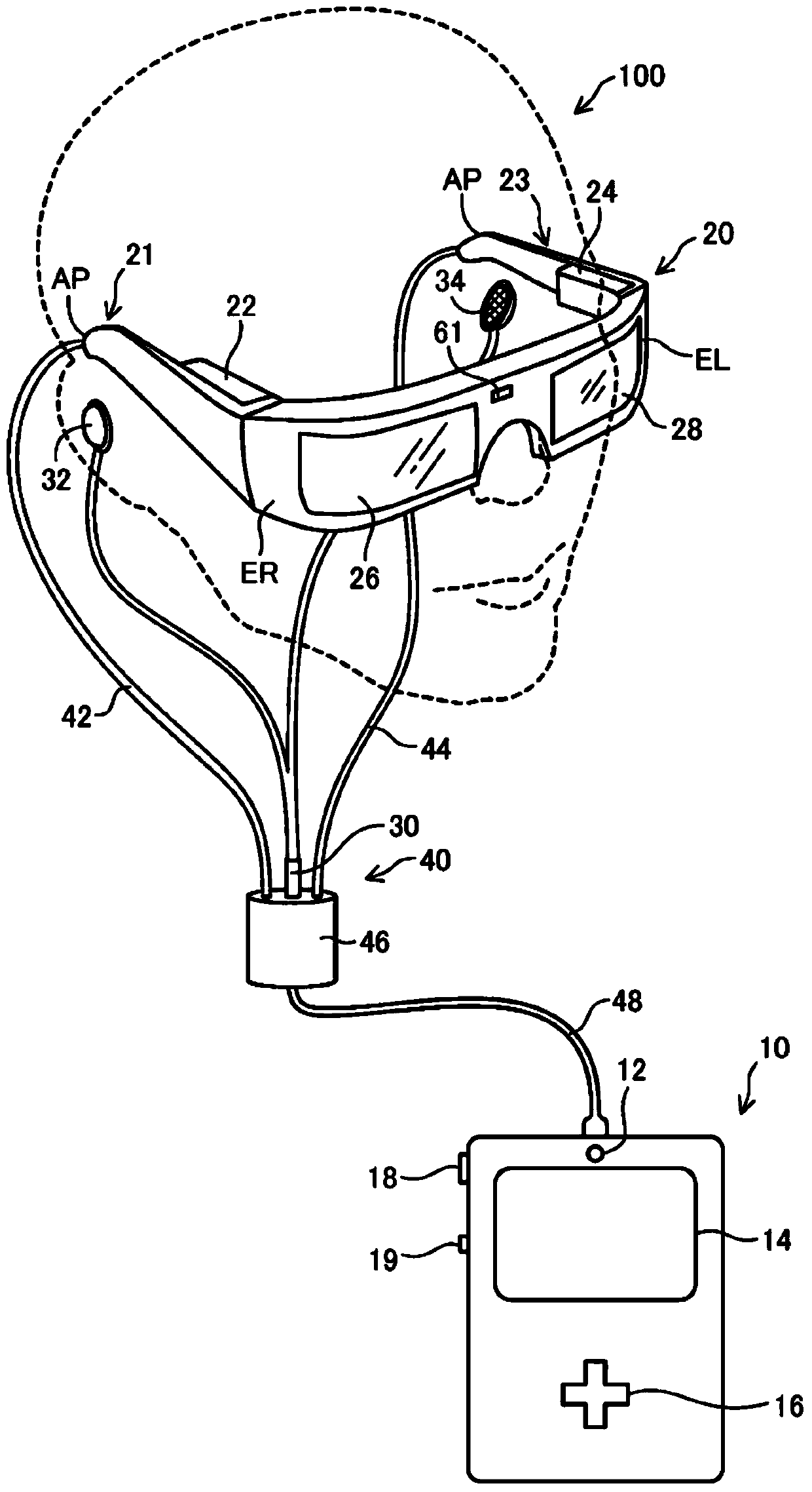
[0066] figure 1 It is an explanatory diagram showing a schematic configuration of a head mounted display device according to an embodiment of the present invention. The head mounted display device 100 is a display device worn on the head, and is also called a head mounted display (Head Mounted Display, HMD). The head-mounted display 100 of the present embodiment is an optical see-through head-mounted display device in which a user can visually recognize a virtual image and also directly visually recognize an external scene. In addition, in this embodiment, the head-mounted display 100 of the type which makes a user visually recognize a video as a virtual image is illustrated.

[0067] The head-mounted display 100 includes an image display unit 20 that allows the user to visually recognize a virtual image while being worn on the user's head, and a control unit (controller) 10 that controls the image display unit 20...

no. 2 Embodiment approach

[0169] In the second embodiment of the present invention, a configuration capable of assisting the work performed by the user in the head-mounted display device will also be described. Hereinafter, only parts having configurations and operations different from those of the first embodiment will be described. In addition, in the drawings, the same reference numerals as those of the first embodiment described above are assigned to the same components as those of the first embodiment, and detailed descriptions thereof will be omitted.

[0170] B-1. Composition of the head-mounted display device:

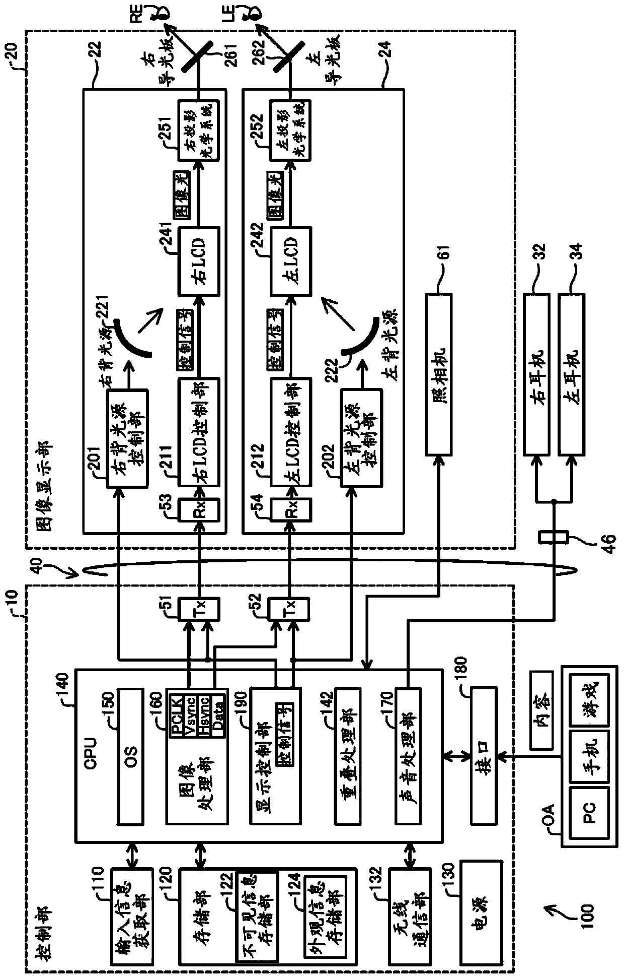
[0171] Figure 13 It is a block diagram functionally showing the configuration of the head-mounted display 100a in the second embodiment. and figure 2 The difference of the first embodiment shown is that a control unit 10 a is provided instead of the control unit 10 . The control unit 10 a is provided with a storage unit 120 a instead of the storage unit 120 , and is provided with ...

no. 3 Embodiment approach

[0205] In the third embodiment of the present invention, in the superimposition information display processing of the first embodiment, "information that does not appear in the appearance of an object (superimposition information)" and "object to be superimposed information display processing A configuration that further improves the accuracy of superimposition of "real images" will be described. Hereinafter, only parts having configurations and operations different from those of the first embodiment will be described. In addition, in the drawings, the same reference numerals as those of the first embodiment described above are assigned to the same components as those of the first embodiment, and detailed descriptions thereof will be omitted.

[0206]C-1. Composition of the head-mounted display device:

[0207] Figure 19 It is an explanatory diagram showing the schematic configuration of the head-mounted display 100b in the third embodiment. Figure 20 It is a block diagra...


PUM


Abstract

The invention provides a head mounted display which enables a real image of an object in a visual field direction and information which is not shown in an appearance of the object to be visually recognized by a user together without the user moving his / her visual line. The head mounted display which allows a user to visually recognize a virtual image and external scenery, and includes an image display unit that forms the virtual image which is visually recognized by the user, and a superimposition processing unit that causes the image display unit to form the virtual image based on superimposition information for superimposing invisible information which is not shown in an appearance of an object on the object included in the external scenery.

Description

technical field [0001] The present invention relates to a head mounted display device. Background technique [0002] A head-mounted display device (Head Mounted Display (HMD)) which is a display device worn on the head is known. For example, the HMD uses a liquid crystal display and a light source to generate image light representing an image, and then uses a projection optical system, a light guide plate, etc. to guide the generated image light into the user's eyes, thereby allowing the user to recognize a virtual image. [0003] Patent Document 1 describes a surgical imaging system and a surgical robot using such a head-mounted display device. In the technique described in Patent Document 1, the user (operator) of the head-mounted display device visually confirms the image observed by the endoscope inserted into the patient's body cavity as a virtual image, and operates the surgical manipulator to perform the operation. . Patent Document 2 describes a medical face-mount...

Claims


Application Information

Patent Timeline
IPC IPC(8): G02B27/01G09G5/00
CPCA61B6/461G02B2027/0138A61B6/462A61B6/5229A61B2019/5229G02B2027/014G02B27/017A61B2019/262G02B2027/0187G02B27/0093A61B2090/502A61B2090/372G02B27/0101G06T5/00G02B27/0172G02B2027/0178G06F3/013G06T19/006
Inventor 高野正秀津田敦也
Owner SEIKO EPSON CORP
Why Eureka
Try Eureka