
Method for detecting and controlling temperatures of processor
A detection control and processor technology, which is applied in the direction of temperature control and hardware monitoring by electric means, can solve the problems of increasing the layout and wiring of the main board, and increasing the design cost of the main board, so as to achieve the effect of improving control accuracy and reducing dependence.
- Summary
- Abstract
- Description
- Claims
- Application Information
AI Technical Summary
Problems solved by technology
Method used
Image

Examples
Embodiment Construction
[0016] The method of the present invention is described in detail below with reference to the accompanying drawings.
[0017] In order to further illustrate the technical means and effects adopted by the present invention, the specific implementation of the present invention will be described in detail below in conjunction with the accompanying drawings.
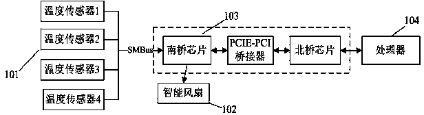
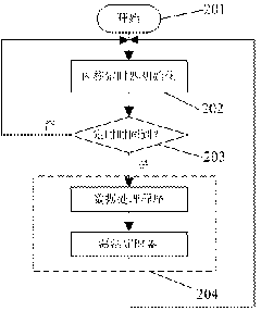
[0018] Such as figure 1 As shown, it is a schematic diagram of the system structure of a specific embodiment of the present invention, including: a temperature sensor 101 , an intelligent fan 102 , a data communication line 103 and a processor 104 . There are also an initialization module 201 , a kernel timer initialization module 202 , a timer overtime judging module 203 and a timer interrupt handler module 204 .
[0019] In this example, the temperature sensor 101 is composed of four temperature sensors with SMBus bus interface, which are respectively installed on the outside of the four edges of the processor, and connec...
PUM
 Abstract
Description
Claims
Application Information