
A high power input coupler

An input coupling and high-power technology, applied in the microwave field, can solve the problems of difficulty, manufacturing and impedance matching increase, and achieve the effect of reducing the difficulty of welding and reducing reflection loss

Inactive Publication Date: 2016-08-24
INST OF HIGH ENERGY PHYSICS CHINESE ACAD OF SCI
View PDF2 Cites 0 Cited by
  • Summary
  • Abstract
  • Description
  • Claims
  • Application Information

AI Technical Summary

Problems solved by technology

However, no matter what type of structure the power input coupler is, it is necessary to connect the power source to the main transmission line of the coupler. The structural design of the connector may use a doorknob conversion structure [Document 1, Mircea Stirbet, Fundamental Power Couplers for the SNSProject, review of the SPL RF coupler CERN 16-17March 2010], or adopt a direct connection structure [Document 2, Q.S.Shu, J.Susta, G.F.Chen et all. "INNOVATIVE MODULAR, MULTIPLE POWER LEVELS, 325MHz SPOKES CAVITIES POWER COUPLERS" , Proceedings of PAC07, New Mexico, USA], for the structure of the window in the coupler, cylindrical windows are commonly used internationally [Document 3, V.Veshcherevich, I.Bazarov et all. "A High Power CW Input Coupler for Cornell ERL Injector Cavities", Cornell University, Tthaca, NewYork] and coaxial flat-shaped windows [Document 1] to isolate the vacuum, which increases the difficulty of the processing and impedance matching of the window itself

Method used


Image

  • A high power input coupler
  • A high power input coupler
  • A high power input coupler

Examples


Embodiment Construction

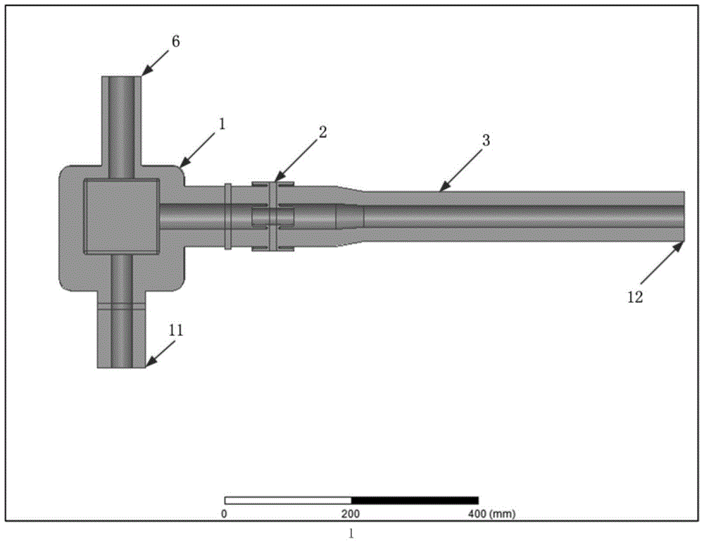
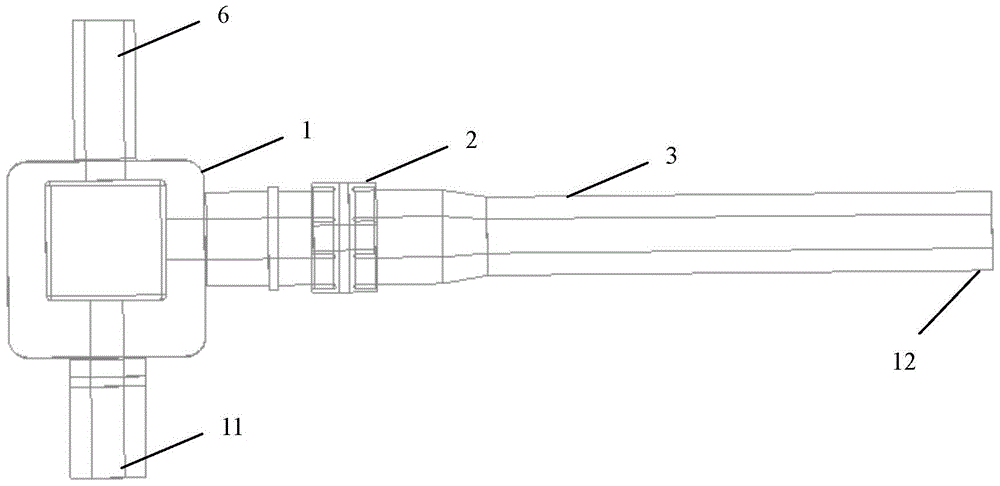
[0039] 1. Using high-frequency electromagnetic field simulation calculation program, complete as attached figure 2 , 3 The dimension design and optimization of the high-frequency structure of the coupler shown in the figure ensure that the coupler realizes the matching transmission of microwave power at the working frequency.

[0040] The high-frequency electromagnetic model of the present invention is as figure 2 and 3 As shown, it mainly includes three components, a T-shaped tuning device 1 , a set of high-frequency windows 2 with a Choke structure, and a 50-ohm coaxial transmission line 3 . The T-shaped tuning device includes an input end, a short-circuit end and an output end; wherein, the input end and the short-circuit end are located on the same axis, and the axis of the output end is perpendicular to the axis of the input end, so that the power transmission direction of the output end is perpendicular to the power transmission direction of the input end. Microwave...


PUM


Abstract

The invention discloses a high-power input coupler. The output end of the high-power input coupler is connected with a coaxial cable through a high-frequency window comprising a Choke structure, wherein the Choke structure comprises an inner conductor Choke structure, an outer conductor Choke structure and a coaxial slab ceramic wafer; the inner conductor Choke structure and the outer conductor Choke structure respectively comprise an upper end and a lower end which are located on the two sides of the coaxial slab ceramic wafer; the upper end and the lower end of the inner conductor Choke structure are respectively in sealed and electrical connection with an inner conductor of the coaxial cable of the output end and are in sealed connection with the coaxial slab ceramic wafer through a coaxial metal frame; the upper end and the lower end of the outer conductor Choke structure are respectively in sealed and electrical connection with an outer conductor of the coaxial cable of the output end and are in sealed connection with the coaxial slab ceramic wafer through a coaxial metal frame. The matched transmission near the window can be achieved, reflection losses are reduced, and at the same time, the welding difficulty of windows is largely reduced.

Description

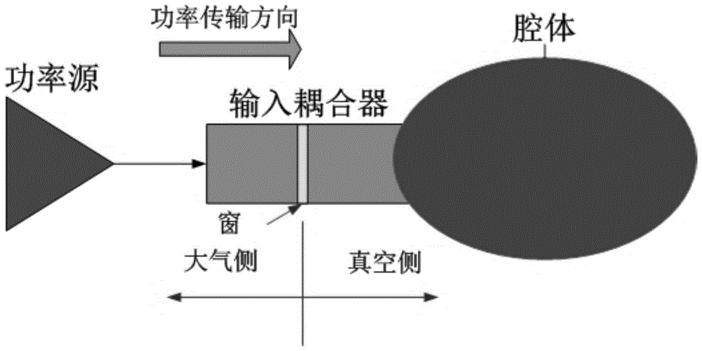
technical field [0001] The invention relates to a high-power input coupler, which belongs to the microwave field. Background technique [0002] The high-power input coupler is essentially a microwave transmission element. It is one of the key components of the radio frequency superconducting system of the particle accelerator. It is located between the power source and the superconducting cavity in the radio frequency superconducting system. Its main function is to transmit microwave Power is fed into the superconducting cavity (see attached figure 1 ), and also use the ceramic window to isolate the atmosphere from the ultra-high vacuum environment, and undertake multiple functions such as the low-leakage heat transition connection from room temperature to superconducting low temperature. [0003] According to operating experience, the high-power input coupler is one of the most fragile key components in the RF superconducting system. Once damaged, the entire accelerator wi...

Claims


Application Information

Patent Timeline
Patent Type & Authority Patents(China)
IPC IPC(8): H01P5/04
Inventor 潘卫民陈旭黄彤明马强孟繁博林海英
Owner INST OF HIGH ENERGY PHYSICS CHINESE ACAD OF SCI
Learn More