Vehicle power transmission system

A power transmission device and power transmission technology, applied in the direction of power devices, multi-ratio transmissions, transmissions, etc., can solve the problems of large speed change shocks and changes, and achieve the effect of suppressing the reduction of vehicle speed

Active Publication Date: 2014-08-20
TOYOTA JIDOSHA KK
View PDF6 Cites 8 Cited by
  • Summary
  • Abstract
  • Description
  • Claims
  • Application Information

AI Technical Summary

Problems solved by technology

This is done because it is considered that when the gear section is switched under the driving state of the ve...

Method used


Image

  • Vehicle power transmission system
  • Vehicle power transmission system
  • Vehicle power transmission system

Examples


Embodiment approach -

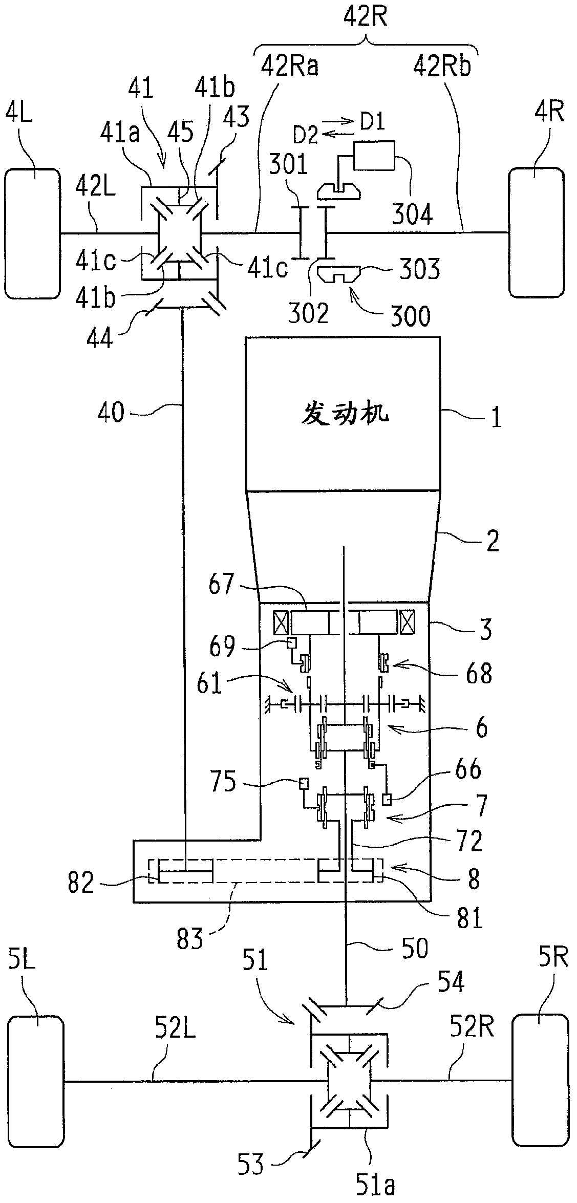
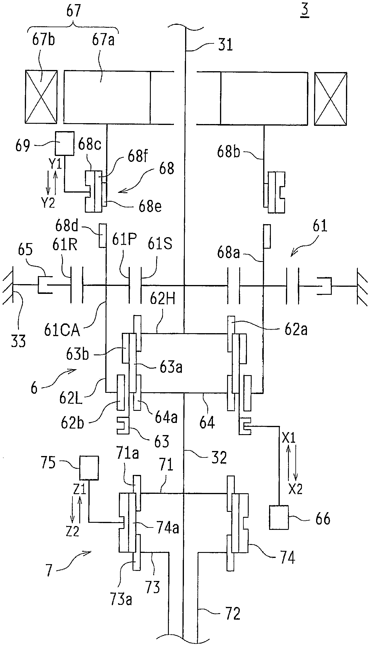
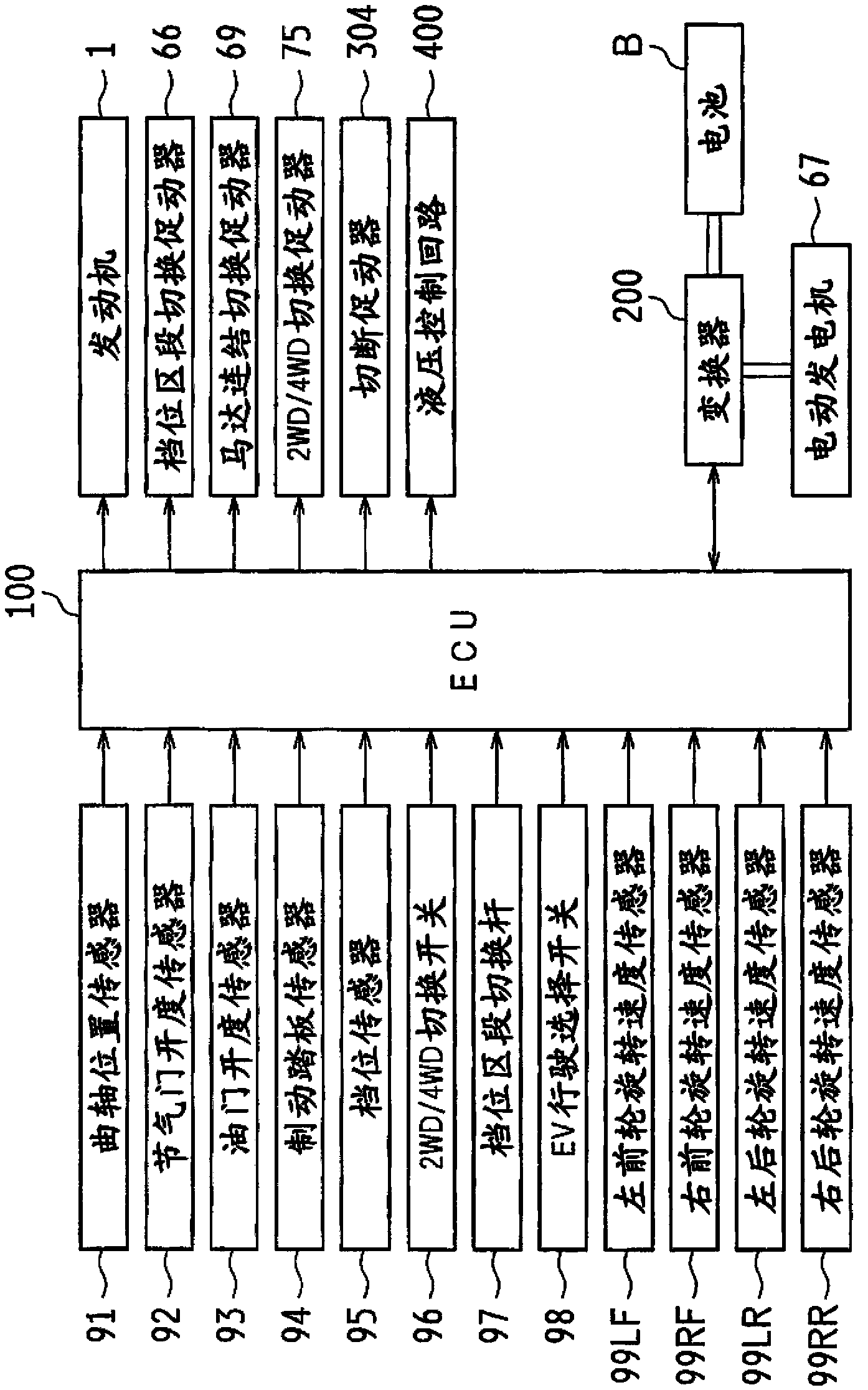
[0180] In the embodiments and modifications described above, a case where the present invention is applied to a four-wheel drive vehicle based on the FR system has been described. The present invention is not limited thereto, and can also be applied to four-wheel drive vehicles based on the FF (Front Engine Front Drive) system.

[0181] In addition, in the above-mentioned embodiments and modified examples, the case where the present invention is applied to a four-wheel drive vehicle capable of switching between the two-wheel drive state and the four-wheel drive state has been described. The present invention is not limited thereto, and can also be applied to vehicles running in a four-wheel drive state (full-time 4WD vehicles), two-wheel drive vehicles (without the 2WD / 4WD switching mechanism 7 and the power split mechanism 8 but with auxiliary transmission Agency 6 vehicle).

[0182] In addition, in the above-mentioned embodiments and modified examples, the electric motor is...


PUM


Abstract

A motor generator (67) is connected to carriers (61CA) of an auxiliary transmission mechanism (6) capable of switching between a high-speed range and a low-speed range, in a manner that enables power to be transmitted to a vehicle provided with said auxiliary transmission mechanism (6). When switching from the high-speed range to the low-speed range, the rotational speed of the carriers (61CA) is increased by the motor generator (67) so as to synchronize the rotational speed of low-speed range pieces (62L) with the rotational speed of an input shaft (31). When switching from the low-speed range to the high-speed range, the rotational speed of the carriers (61CA) is increased by the motor generator (67) so as to synchronize the rotational speed of an output shaft (32) with the rotational speed of the input shaft (31). Thus, range switching can be performed while reducing transmission shocks, even while the vehicle is moving.

Description

technical field [0001] The present invention relates to a power transmission device of a vehicle. In particular, the present invention relates to an improvement of a mechanism for switching gear ratios in a power transmission path. Background technique [0002] Conventionally, as shown in Patent Document 1 and Patent Document 2 below, for example, there are known four-wheel drive vehicles having an auxiliary transmission for further shifting the rotational output shifted by the main transmission. Such splitters are generally range-switchable between a high range (Hi) and a low range (Lo). [0003] As a mechanism for switching the gear range, as shown in each patent document, there is a sleeve movable along the axis of the output shaft of the main transmission, and the high-speed side ( The power transmission path is switched between the side with a small gear ratio) and the low speed side (side with a large gear ratio). [0004] Normally, the range switching of the auxili...

Claims


Application Information

Patent Timeline
IPC IPC(8): F16H61/02B60L50/16
CPCB60K2006/4808B60K6/52B60W30/19F16H3/54Y02T10/626B60K6/547Y02T10/6265F16H2200/2094F16H3/78F16H2200/2064B60W10/08F16H2200/2035B60W20/00F16H3/725F16H37/046F16H2200/2005Y02T10/6221B60K17/346B60K6/48F16H61/32F16H2061/323F16H2003/447F16H2200/0034F16H2200/2038Y02T10/62Y02T10/72B60K17/04B60K17/06B60K6/36
Inventor 杉本隆幸
Owner TOYOTA JIDOSHA KK
Why Eureka
Try Eureka