Supercapacitor cleaning and drying device and cleaning and drying method
A supercapacitor and drying device technology, applied in the direction of drying gas arrangement, chemical instruments and methods, cleaning methods and utensils, etc., can solve the problems of poor cleaning effect and low drying efficiency, and achieve the advantages of water shedding, high drying efficiency, and structural Simple and practical effect
- Summary
- Abstract
- Description
- Claims
- Application Information
AI Technical Summary
Problems solved by technology
Method used
Image

Examples
Embodiment Construction
[0017] The present invention will be further described below in conjunction with the accompanying drawings.
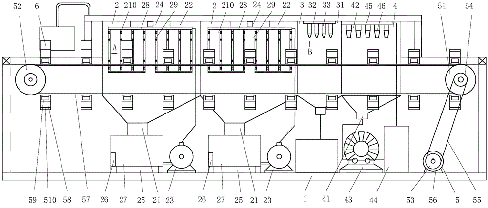
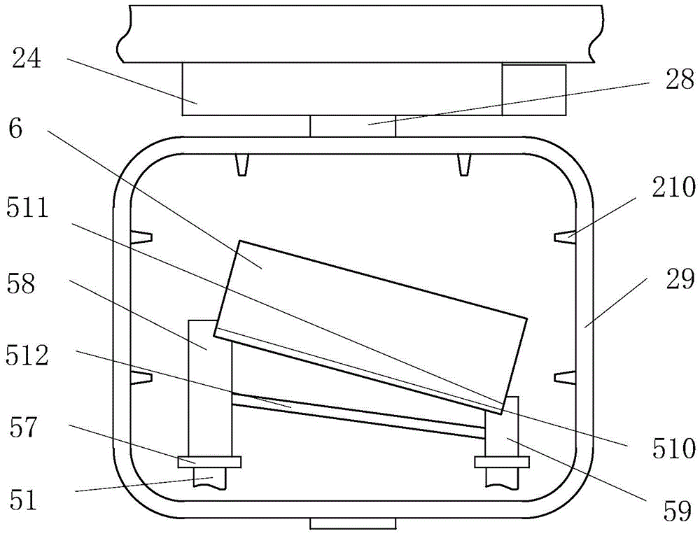
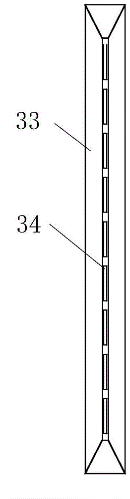
[0018] as attached figure 1 , attached figure 2 , attached image 3 Shown: a supercapacitor cleaning and drying device, including a frame 1, a conveying mechanism 5 with a conveyor belt, two high-pressure cleaning chambers 2, a liquid blowing drying chamber 3 and a drying chamber 3 arranged in sequence along the front and rear and sleeved outside the conveyor belt The dry room 4 and the high-pressure cleaning room 2 have ring-shaped spray pipe groups sleeved outside the conveyor belt.
[0019] The high-pressure cleaning chamber 2 includes a cleaning chamber housing 22 with a liquid return port 21 at the bottom and screwed to the frame 1, a high-pressure water pump 23, a transverse slide 24, a water tank 27 with an electric heating tube 25 and a temperature controller 26; Annular shower pipe group comprises communicating pipe 28 and eight annular shower pipes 29 tha...
PUM
 Abstract
Description
Claims
Application Information
 - R&D
- Intellectual Property
- Life Sciences
- Materials
- Tech Scout
- Unparalleled Data Quality
- Higher Quality Content
- 60% Fewer Hallucinations
Browse by: Latest US Patents, China's latest patents, Technical Efficacy Thesaurus, Application Domain, Technology Topic, Popular Technical Reports.
© 2025 PatSnap. All rights reserved.Legal|Privacy policy|Modern Slavery Act Transparency Statement|Sitemap|About US| Contact US: help@patsnap.com