
Forging process for adopting centrifugal casting hollow ingots to produce ring-shaped parts and cylindrical parts

A technology of centrifugal casting and hollow ingot, which is applied in the field of forging, can solve the problems of many blanks, multiple firing times, and low material yield, and achieve the effects of reducing energy consumption, reducing energy consumption, and increasing yield

Inactive Publication Date: 2014-08-27
CHINA IRON & STEEL RES INST GRP +1
View PDF5 Cites 6 Cited by
  • Summary
  • Abstract
  • Description
  • Claims
  • Application Information

AI Technical Summary

Problems solved by technology

The disadvantages of this forging method are: ① more blanks are required, the process flow is lengthy, too many fires, and more energy consumption; ② the center material of the solid blank is treated as waste in the punching process, and the material yield is low

Method used


Image

  • Forging process for adopting centrifugal casting hollow ingots to produce ring-shaped parts and cylindrical parts
  • Forging process for adopting centrifugal casting hollow ingots to produce ring-shaped parts and cylindrical parts

Examples


Embodiment 1

[0023] Embodiment 1: The present invention will be further described by taking the forging test of a 316LN stainless steel cylinder used in a certain nuclear power plant as an example.

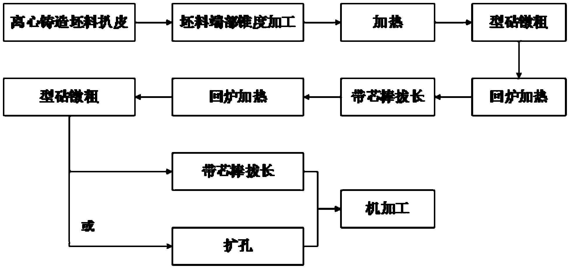
[0024] Such as figure 1 Shown, be the technical process block diagram of the present invention and its implementation example, specifically comprise the following process steps:

[0025] In the first step, after the chemical composition analysis, peeling of the inner and outer surfaces of the pipe as required, processing of pipe end taper and flaw detection, the centrifugally cast hollow ingot with a weight of about 1045kg and a size of Φ480×115×1000mm is sent into the After removing the residual oxides, the furnace is heated according to the six-stage heating curve (the holding time of each stage decreases and the heating speed increases). The furnace entry temperature is 700°C, and the maximum heating temperature is 1180°C.

[0026] The six-stage heating curve refers to: the temperature ri...

Embodiment 2

[0033] Embodiment 2: The present invention will be further described by taking the forging test of a 316LN stainless steel cylinder used in a certain nuclear power plant as an example.

[0034] In the first step, after the chemical composition analysis, peeling of the inner and outer surfaces of the pipe as required, processing of pipe end taper and flaw detection, the centrifugally cast hollow ingot with a weight of about 1045kg and a size of Φ480×115×1000mm is sent into the After removing the residual oxides, the furnace is heated according to the six-stage heating curve (the holding time of each stage decreases and the heating speed increases). The furnace entry temperature is 700°C, and the maximum heating temperature is 1180°C.

[0035] The six-stage heating curve refers to: the temperature rise of the cold ingot below 700°C is regarded as the first stage, the heat preservation at 850°C is regarded as the second stage, and the heating from 850°C to 950°C is regarded as th...


PUM


Abstract

The invention relates to a forging process for adopting centrifugal casting hollow ingots to produce ring-shaped parts and cylindrical parts and belongs to the technical field of forging. The process comprises the steps of peeling and flaw detection of inner and outer surfaces of the casting hollow ingots, heating, hollow body upsetting on swage blocks in special design, heating, core rod drawing out, heating, hollow body upsetting on swage blocks in special design, heating, core rod drawing out to a needed dimension or pore broadening to a required dimension. Compared with a forging forming process for which solid ingots are widely adopted, the forging forming process has the comparative advantages of obviously improving the material yield, saving energy and reducing consumption.

Description

technical field [0001] The invention belongs to the technical field of forging, and in particular relates to a forging process for producing ring parts and cylindrical parts by adopting centrifugal casting hollow ingots. Background technique [0002] Large rings and cylinders are mainly used in important fields such as electric power, construction machinery, and military industry, because the conditions of use are usually relatively harsh, and the performance requirements of the products are extremely high. Typically, large rings and barrels are forged and then machined to form the final product. At present, the method of forging large-scale ring tube parts at home and abroad is mainly to use a solid billet, form a hollow billet after heating, upsetting, and punching, and then elongate or expand the hole to the corresponding size. The disadvantages of this forging method are: (1) more blanks are required, the process flow is lengthy, too many fires, and more energy consumpt...

Claims


Application Information

Patent Timeline
IPC IPC(8): B21J1/00B21J5/00B21J5/08
Inventor 李殿杰王金飞李胜峰韩宝云张波
Owner CHINA IRON & STEEL RES INST GRP
Learn More