

Thin layer fast solidification forming device and method
A solidification molding and thin-layer technology, applied in the field of material processing, can solve the problems of low production efficiency, high production cost, unsuitable for large ingot production, etc., and achieve the effect of high production efficiency, low cost and uniform distribution of components
- Summary
- Abstract
- Description
- Claims
- Application Information
AI Technical Summary
Problems solved by technology
Method used
Image

Examples
Embodiment 1
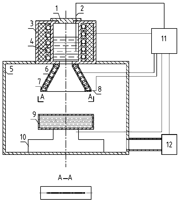
[0021] see figure 1 , the thin layer rapid solidification forming device layer by layer, including crucible sealing cover (1), crucible temperature measuring element (2), crucible (3), crucible heater (4), vacuum chamber (5), nozzle heater ( 6), nozzle (7), nozzle temperature measuring element (8), forced cooling platform (9), three-dimensional mobile platform (10), microcomputer control system (11), vacuum pump (12), characterized in that: the crucible is sealed The crucible system composed of cover (1), crucible temperature measuring element (2), crucible (3) and crucible heater (4) is fixed above the vacuum chamber (5); the upper end of the nozzle (7) communicates with the bottom of the crucible (3), Located in the vacuum chamber (5); the forced cooling platform (9) is located directly below the lower end of the nozzle (7) and connected to the upper part of the three-dimensional mobile platform (10); the three-dimensional mobile platform (10) is placed on the bottom of the...
Embodiment 2
[0023] This embodiment is basically the same as Embodiment 1, and the features are as follows:
[0024] The lower end of the nozzle (7) is in the shape of a narrow slit with a width of 0.1-100mm and a length of 1-2000mm. The flow rate of molten metal flowing out of the nozzle is controlled at 0-1000m / s. Temperature measuring elements (2, 8) connected to the microcomputer control system (11) are respectively placed inside the crucible (3) and on the outer wall of the nozzle (7), and heaters ( 4, 6). There is circulating cooling water in the forced cooling table (9), and the cooling water temperature is set to 20 o c. After the temperature is set in the microcomputer control system (11), the temperature can be controlled through the temperature measuring element and the heater connected to it; the microcomputer control system (11) stores the size data of the parts to be processed, and then the parts The three-dimensional model is layered, and then the displacement of the thr...
Embodiment 3
[0026] In this embodiment, the steps of preparing metal parts by adopting the thin-layer rapid solidification molding device of the present invention are as follows:
[0027] 1). Open the crucible cover (1), add 22 kg of Al-17%wt.Si alloy into the crucible (3), then input the part size 0.2m×0.2m×0.2m into the microcomputer control system (11), and Perform layering and trajectory setting;
[0028] 2). Seal the crucible lid (1) and the vacuum chamber (5), and evacuate;
[0029] 3). Set the heating temperature of the crucible in the microcomputer control system (11) to 750 oC , and then start the crucible heater (4) to melt the Al-Si alloy.
[0030] 4). In the microcomputer control system (11), set the nozzle heating temperature to 700 oC , and then start the nozzle heater (6) to heat the nozzle;
[0031] 5). Start the forced cooling platform (9) and the three-dimensional mobile platform (10), so that the thin metal layer flowing out of the slit-shaped nozzle is continuousl...
PUM
| Property | Measurement | Unit |
|---|---|---|
| width | aaaaa | aaaaa |
| length | aaaaa | aaaaa |
Abstract
Description
Claims
Application Information