Intelligent cam numerically controlled lathe and control system thereof

A control system and technology of CNC lathes, applied in the field of CNC lathes, can solve problems such as poor consistency, high labor intensity, and unguaranteed machining accuracy

Inactive Publication Date: 2014-08-27
孙小东 +2
View PDF6 Cites 6 Cited by
  • Summary
  • Abstract
  • Description
  • Claims
  • Application Information

AI Technical Summary

Problems solved by technology

[0003] The purpose of the present invention is to provide an intelligent cam CNC lathe and its control system, aiming to solve the problems of the existing cam lathes with high labor intensity, low processing efficiency, poor consistency, unguaranteed processing accuracy, and inability to adapt to the production of current high-precision parts. The problem

Method used


Image

  • Intelligent cam numerically controlled lathe and control system thereof

Examples


Embodiment Construction

[0015] In order to make the object, technical solution and advantages of the present invention clearer, the present invention will be further described in detail below in conjunction with the accompanying drawings and embodiments. It should be understood that the specific embodiments described here are only used to explain the present invention, not to limit the present invention.

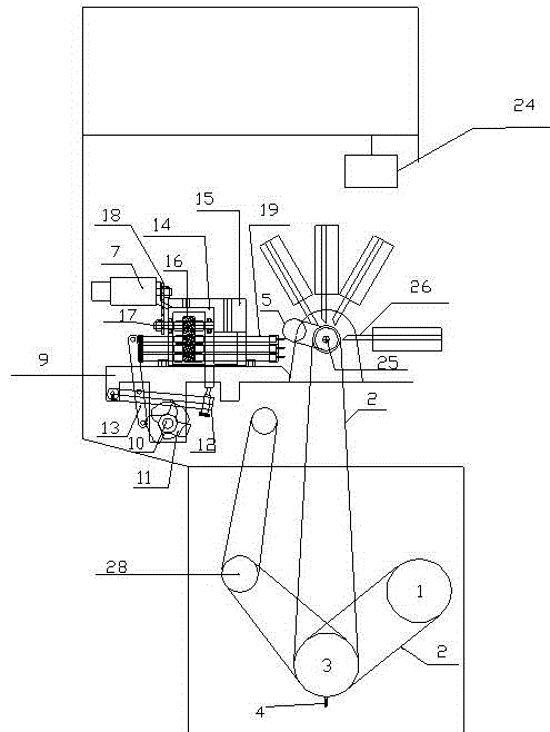
[0016] figure 1 The structure of the intelligent cam numerical control lathe of the present invention is shown, as shown in the figure, the present invention is realized in this way, a kind of intelligent cam numerical control lathe comprises machine bed, machine tool power part, side power unit, machine tool shell, numerical control touch screen 24 , PLC control system, servo driver, electrical control circuit board;

[0017] The power part of the machine tool includes a servo motor 1, a timing belt 2, a transmission shaft 3, a sensor 4, an encoder 5, and a pneumatic valve switch clip 6;

[001...


PUM


Abstract

The invention discloses an intelligent cam numerically controlled lathe and a control system thereof. The intelligent cam numerically controlled lathe comprises a lathe body, a lathe power part, a side face power device, a lathe shell, a numerically controlled touch screen, a PLC control system, a servo driver and an electrical control circuit board. According to the lathe power part, a PLC controls an electric servo mainframe to drive a transmission shaft through a synchronous belt, then a lathe spindle is driven through the synchronous belt with the ratio of transformation being 1 to 2, a spring collet is locked through a pneumatic valve switch, materials are driven to rotate to the angle at which machining can be performed through the side face power device, the lathe brakes and stops working or rotates any angle or rotates at high speed so that a tool of the lathe itself or a tool additionally arranged on the side face of the lathe can perform machining of all procedures on the materials. The intelligent cam numerically controlled lathe solves the problem that an existing lathe can only perform machining of partial procedures on workpieces, and can complete machining of all the procedures without secondary machining.

Description

technical field [0001] The invention belongs to the field of numerical control lathes, in particular to an intelligent cam numerical control lathe and its control system. Background technique [0002] Automatic cam lathes in the existing market. Only five groups of tools in the longitudinal direction can be used for turning, but not chamfering, drilling, tapping, milling Pozier grooves, flat side milling, and multi-square milling on any side. The material must be turned into a blank, and the blank is taken down and then chamfered, drilled, tapped by a tapping machine, and milled by a milling machine. Milling machine flat-milling, polygon milling, etc. This processing method is not only labor-intensive, but also low-efficiency, poor consistency, processing accuracy cannot be guaranteed, and is not suitable for the current production of high-precision parts. Contents of the invention [0003] The purpose of the present invention is to provide an intelligent cam CNC lathe a...

Claims


Application Information

Patent Timeline
Patent Type & Authority Applications(China)
IPC IPC(8): B23B7/00B23Q5/02G05B19/18
CPCB23B7/00B23Q5/02
Inventor 孙小东谢昌辽李志辉
Owner 孙小东
Why Eureka
Try Eureka