Pressure maintaining and speed stabilizing hydraulic system of hydraulic machine

A hydraulic system and hydraulic press technology, applied in the field of hydraulic press hydraulic system, can solve the problems of sheet material deformation and damage, and achieve the effect of high work efficiency

Inactive Publication Date: 2014-08-27
南通东海机床制造集团有限公司 +1
View PDF16 Cites 9 Cited by
  • Summary
  • Abstract
  • Description
  • Claims
  • Application Information

AI Technical Summary

Problems solved by technology

If the pressure fluctuates or the speed of movement changes during the process of pressing the plate by the hydraulic press, it will cause shock, vibration, noise of the hydraulic system and even cause deformation and destruction of the plate material.

Method used


Image

  • Pressure maintaining and speed stabilizing hydraulic system of hydraulic machine

Examples


Embodiment Construction

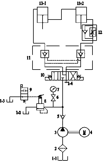
[0013] Such as figure 1 As shown, the hydraulic system of the hydraulic press of the present invention includes a fuel tank 1, a filter 2, a hydraulic pump 3, a motor 4, a check valve 5, a pressure gauge switch 6, a pressure gauge 7, a pilot relief valve 8, and a two-position two-way electromagnetic Reversing valve 9, three-position four-way electromagnetic reversing valve 10, double hydraulic control check valve 11, one-way speed regulating valve 12, hydraulic cylinder 13.

[0014] When the hydraulic machine is working, the motor 4 drives the hydraulic pump 3 to suck out the oil in the oil tank 1 through the filter 2, and the oil is divided into two paths through the check valve 5; one path passes through the pilot relief valve 8 and the two-position two-way electromagnetic The reversing valve 9 returns to the fuel tank 1; this oil circuit can realize the functions of pressure regulation and unloading of the hydraulic system. The other oil circuit enters the rodless chamber ...


PUM


Abstract

The invention provides a pressure maintaining and speed stabilizing hydraulic system of a hydraulic machine. The pressure maintaining and speed stabilizing hydraulic system comprises an oil tank, a filter, a hydraulic pump, a motor, a one-way valve, a pilot operated compound relief valve, a two-position two-way electromagnetic directional valve, a three-position four-way electromagnetic directional valve, a double-hydraulic-control one-way valve and a one-way speed regulating valve. When the hydraulic machine works in the feeding working station, the left position of the three-position four-way electromagnetic directional valve is connected; oil liquid enters a first hydraulic cylinder rodless cavity through the one-way valve, the three-position four-way electromagnetic directional valve and the left one-way valve in the double-hydraulic-control one-way valve under the effect of the hydraulic pump; oil liquid in a rod cavity enters a second hydraulic cylinder rodless cavity through a pipe and returns to the oil tank through a speed regulating valve body in the one-way speed regulating valve, and a valve opening of the speed regulating valve body is set to be capable of achieving the stability of the motion speed of the hydraulic machine during feeding. The hydraulic system of the hydraulic machine has the advantages of being remarkable in pressure maintaining effect in the feeding working condition, stable in running speed, rapid in returning and high in efficiency.

Description

technical field [0001] The invention relates to a pressure-maintaining and speed-maintaining hydraulic system of a hydraulic press, which belongs to the technical field of mechanical production control. Background technique [0002] With the continuous development of modern industrial control technology, the hydraulic control system technology of hydraulic presses is becoming more and more mature, and the requirements for its control performance are also getting higher and higher. During the working process of the hydraulic press, its working cycle has three stages: rapid descent, slow pressurization, and rapid return. Among them, the slow pressurization, that is, the working stage, is the focus of the entire hydraulic control process. At this stage, the tool (that is, the upper template) is required to keep the speed of movement stable while pressing the plate with a certain pressure. After the plate is pressed at a constant pressure and constant speed, the tool returns t...

Claims


Application Information

Patent Timeline
Patent Type & Authority Applications(China)
IPC IPC(8): F15B11/05F15B11/22F15B13/06B30B15/16
Inventor 王存堂张先俊谢方伟宣芮盛刚任乃飞王匀童明华
Owner 南通东海机床制造集团有限公司
Why Eureka
Try Eureka