
Indoor positioning system based on LED lamps

A technology for LED lights and indoor positioning, applied in the field of indoor positioning systems based on LED lights, can solve the problems of high cost and complex positioning system structure, and achieve the effect of high positioning accuracy

Inactive Publication Date: 2014-08-27
重庆广建装饰股份有限公司
View PDF2 Cites 27 Cited by
  • Summary
  • Abstract
  • Description
  • Claims
  • Application Information

AI Technical Summary

Problems solved by technology

The structure of these positioning systems is relatively complex and the cost is relatively high.

Method used


Image

  • Indoor positioning system based on LED lamps
  • Indoor positioning system based on LED lamps
  • Indoor positioning system based on LED lamps

Examples


Embodiment Construction

[0020] The present invention will be further described below in conjunction with the accompanying drawings and specific embodiments.

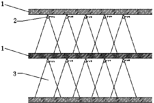
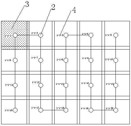
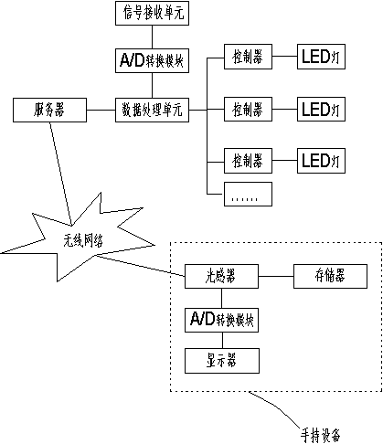
[0021] The indoor positioning system based on LED lights includes LED lights 2, servers and handheld devices. The LED lights 2 are installed on the ceiling of the positioning area, and multiple LED lights 2 are installed in each positioning area. Covers the entire location area with fewer intersections. Each LED light 2 has a unique code and flashing frequency, and the code 4 contains the position information and coordinate information of the LED light in its positioning area. "Position information" includes the floor 1 and partition where the LED light is located, etc., " "Coordinate information" is the coordinate position of the LED lamp 2 in the positioning area map. The coding and flickering frequency of the LED lamps 2 are stored in the database of the server through the network, and the location area map and the position information of e...


PUM


Abstract

The invention discloses an indoor positioning system based on LED lamps. The system comprises the LED lamps, a server and handheld equipment. Each LED lamp has the unique coding and flicker frequency, the coding and flicker frequencies of the LED lamps are stored in the server, a positioning regional map is stored in the server, and the handheld equipment receives light emitted by the LED lamps, converts optical signals into flicker frequency signals of the LED lamps and obtains position information of the LED lamps corresponding to the flicker frequency signals. Signal propagation is achieved through the flicker frequencies of the LED lamps, an optical flame detector is adopted to collect the flicker frequency information of the LED lamps, the indoor precise positioning is achieved through map information prestored in the server, the positioning precision is high, the current position can be precisely positioned, the accuracy can reach within two meters, and the system is suitable for precise positioning of indoor large markets, interiors of buildings, underground markets, underground parking lots and the like.

Description

technical field [0001] The invention relates to the technical field of positioning, in particular to an indoor positioning system based on LED lights. [0002] Background technique [0003] At present, the most used positioning method is the GPS satellite navigation and positioning system. It operates on 6 orbits of the earth through 21 plus 3 spare satellites. Each orbit forms an angle of 120 degrees. , so that at least 4 satellites can be observed at any time and any place on the ground at the same time, and then the distance between the GPS satellite and the receiver is calculated by the signal transmission time length, and then the longitude and latitude of the receiver are determined by the three-point positioning system. 4 satellites to determine the height of the receiver from the ground, and then use the map cached in the receiver to realize positioning and navigation. When using GPS positioning, it is necessary to ensure that there is no deviation in the orbit of ...

Claims


Application Information

Patent Timeline
IPC IPC(8): G01S1/70
CPCG01C21/206G01S1/70
Inventor 王建军
Owner 重庆广建装饰股份有限公司
Learn More