
Automatic assembly machine for electric couplers

A technology for automatic assembly machines and electrical connectors, applied in the assembly/disassembly of contacts, etc., which can solve problems such as defect rate, high scrap rate, low efficiency, and labor

Active Publication Date: 2014-08-27
JIANGSU ZHONGHAI HUA HE ENVIRONMENTAL PROTECTION CO LTD
View PDF5 Cites 17 Cited by
  • Summary
  • Abstract
  • Description
  • Claims
  • Application Information

AI Technical Summary

Problems solved by technology

This structure has the following disadvantages: 1. Manual operation, low efficiency and high difficulty; 2. High risk; 3. Poor quality, high defect rate and scrap rate; 4. Difficult processing and high manufacturing cost

Method used


Image

  • Automatic assembly machine for electric couplers
  • Automatic assembly machine for electric couplers
  • Automatic assembly machine for electric couplers

Examples


Embodiment Construction

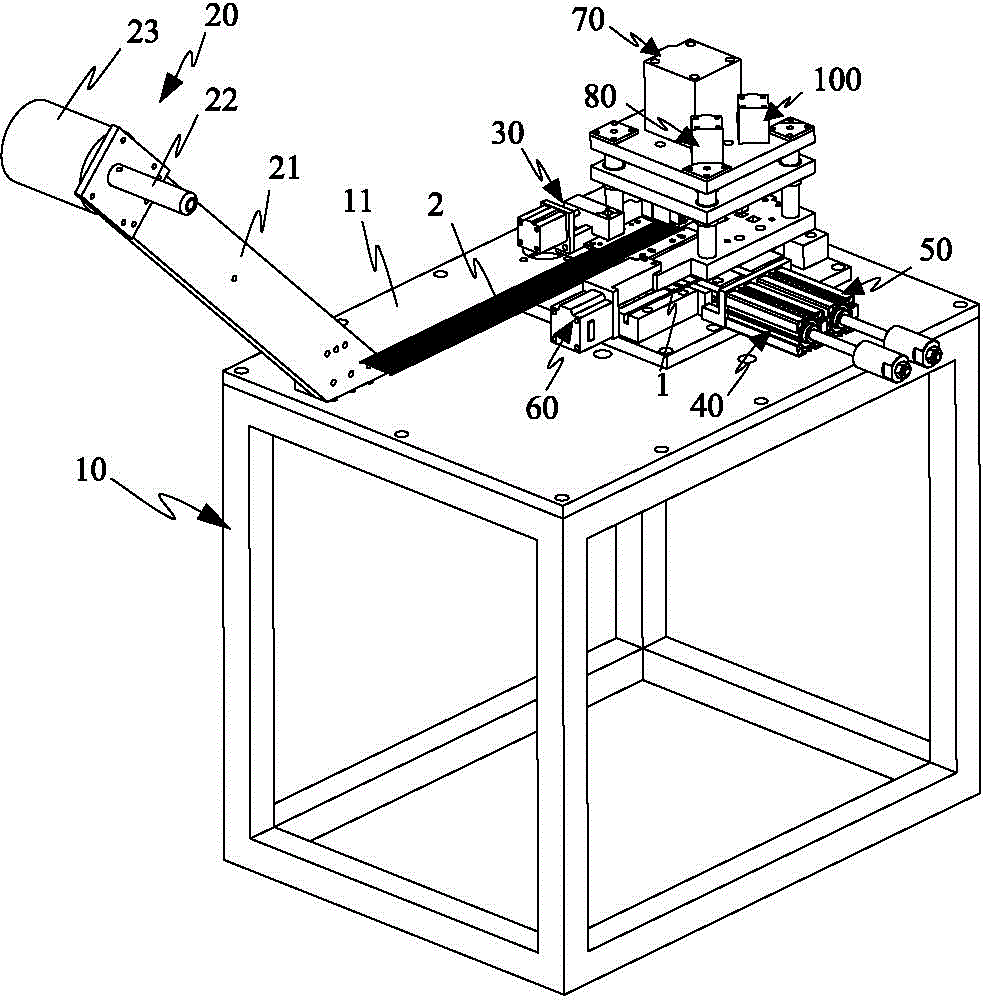
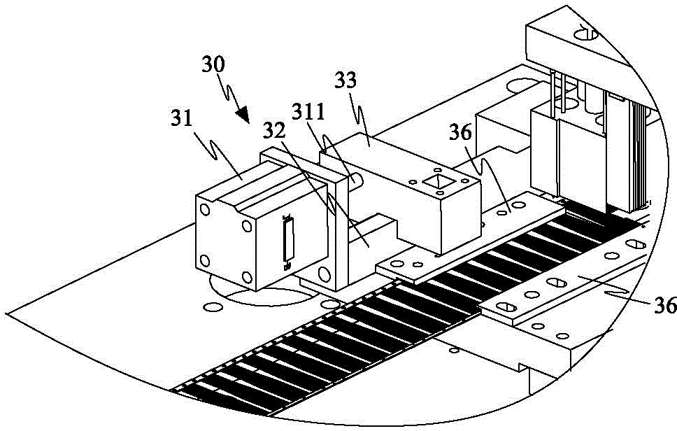
[0065] Please refer to figure 1 As shown, it shows the specific structure of a preferred embodiment of the present invention, including a frame 10, a fixed terminal device 20, a terminal feeding device 30, a first rubber core device 40, a second rubber core device 50, The rubber core pushing device 60 , the terminal cutting device 70 , the terminal pressing device 80 , the primary welding leg folding device 90 , the secondary welding leg folding device 100 and the triple welding leg folding device 110 .

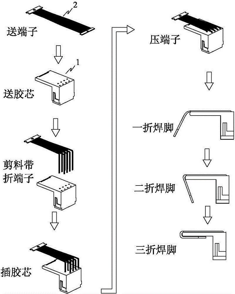
[0066] figure 2 It shows the processing technology of the automatic assembly machine for electrical connectors. First, the terminal 2 is conveyed by the terminal feeding device 30, and the rubber core 1 is conveyed by the first rubber core feeding device 40, the second rubber core feeding device 50 and the rubber core pushing device 60. After the terminal 2 is transported in place, the terminal cutting device 70 presses down to cut off the strip and bends the terminal 2 at ...


PUM


Abstract

The invention discloses an automatic assembly machine for electric couplers. A terminal fixing device, a terminal conveying device, a first rubber core inlet device, a second rubber core inlet device, a rubber core pushing device, a terminal cutting device, a terminal pressing device, a primary weld leg bending device, a secondary weld leg bending device and a third weld leg bending device are integrated on a rack at the same time. By the adoption of the automatic assembly machine for the electric couplers, terminal material belts and rubber cores can be automatically conveyed, terminal material belts can be automatically cut off, bent and pressed, weld legs can be automatically bent, human involvement is not needed in the whole production process of the electric couplers, human cost is greatly reduced, the production speed is increased, and quality of products is improved.

Description

technical field [0001] The invention relates to the technology in the field of automation equipment, in particular to an automatic assembly machine for electrical connectors. Background technique [0002] In order to realize the automation of electronic assembly, according to the needs of the automatic terminal insertion machine, the connected terminals are cut off and inserted into the holes of the connector rubber core one by one. The current semi-automatic equipment for terminal assembly is accompanied by manual operation. This structure has the following disadvantages: 1. Manual operation, low efficiency and high difficulty; 2. High risk; 3. Poor quality, high defect rate and scrap rate; 4. Difficult processing and high manufacturing cost. Contents of the invention [0003] In view of this, the present invention aims at the deficiencies in the prior art, and its main purpose is to provide an automatic assembly machine for electrical connectors, which can not only autom...

Claims


Application Information

Patent Timeline
IPC IPC(8): H01R43/20
Inventor 骆阳旭
Owner JIANGSU ZHONGHAI HUA HE ENVIRONMENTAL PROTECTION CO LTD
Learn More