Temperature compensating circuit for linearly driving LED

A temperature compensation circuit and linear drive technology, applied in the direction of electric lamp circuit layout, electric light source, lighting device, etc., can solve the problems of performance damage such as LED life, continuous thermal opening, inability to timely and accurate shutdown, etc., to achieve The effect of temperature double protection and current adaptive reduction

Inactive Publication Date: 2014-08-27
UNIV OF ELECTRONIC SCI & TECH OF CHINA
View PDF5 Cites 5 Cited by
  • Summary
  • Abstract
  • Description
  • Claims
  • Application Information

AI Technical Summary

Problems solved by technology

[0003] Now, the temperature protection circuit mainly uses the over-temperature shutdown module. On the one hand, this technology is prone to non-stop heating and thermal shutdown. On the other hand, the temperature in this technical solution generally refe

Method used


Image

  • Temperature compensating circuit for linearly driving LED
  • Temperature compensating circuit for linearly driving LED
  • Temperature compensating circuit for linearly driving LED

Examples


Embodiment

[0021] Such as Figure 4 As shown, the over-temperature shutdown module in this example is composed of PMOS transistors PM1, PM2, PM3, PM4, NMOS transistors NM1, NM2, NM3, NM4, NM5, triode NPN1, resistor R1, and inverter INV; among them, PM1, The source of PM2, PM3, PM4 is connected to the power supply VDD; the gate and drain of PM1 are interconnected, the gate is connected to the gate of PM2, and the drain is connected to the drain of NM; the source of NM2 is grounded to GND; NM2, NM1 The gates of NM3, NM5 are interconnected; the source of NM1 is grounded to GND, and the drain and gate are connected to the external current source I_BIAS; the source of PM2 is connected to the power supply VDD, and the drain is connected to the input terminal of the inverter INV and the transistor The collector of NPN1; the emitter of transistor NPN1 is grounded to GND, and its base is connected to the drain of PM4, and its base is also grounded to GND after passing through R1; the source of PM3 ...


PUM


Abstract

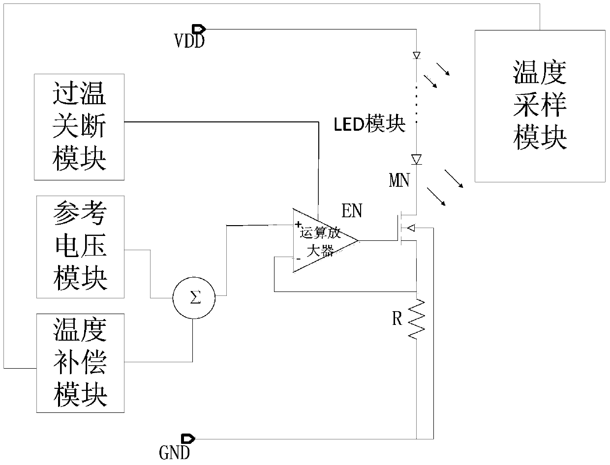
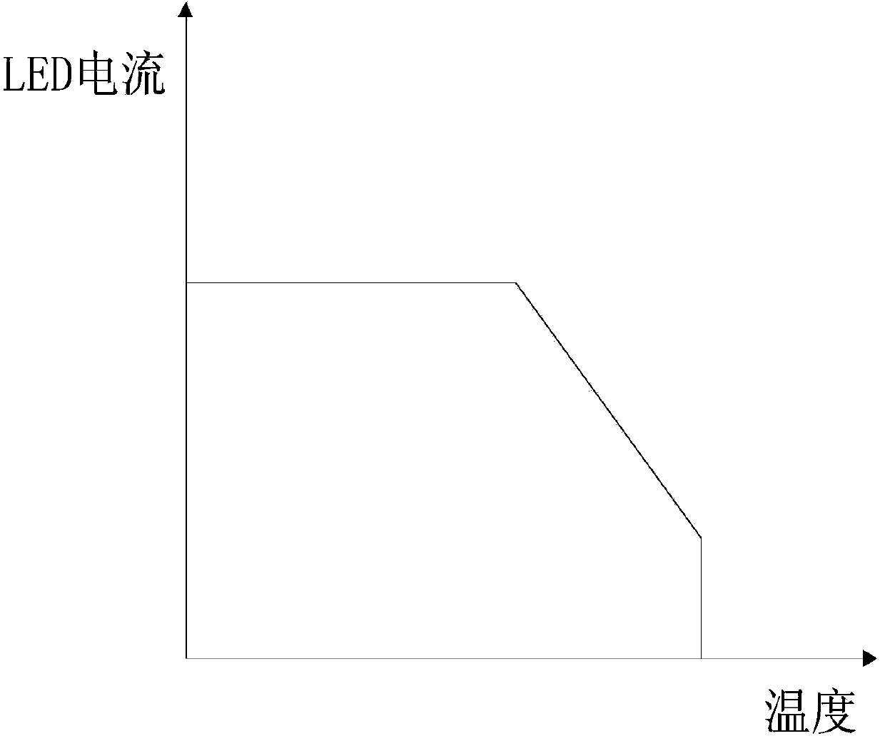
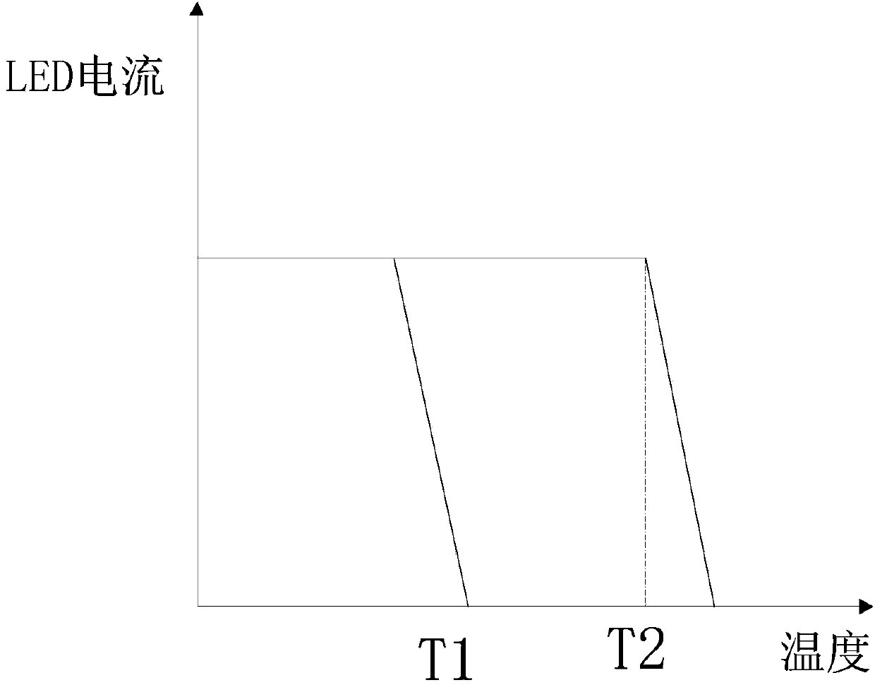
The invention relates to an electronic circuit technology, in particular to a temperature compensating circuit for linearly driving an LED. The circuit is characterized by further comprising an operational amplifier, a driving tube MN and a resistor R, wherein the temperature of an LED module is sampled by a temperature sampling module and the output end of the temperature sampling module is connected with the input end of a temperature compensation module; the output voltage of the temperature compensation module and the output voltage of a reference voltage module are added together and then applied to the positive input end of the operational amplifier; the negative input end of the operational amplifier is connected with a source electrode of the driving tube MN, the enabling end EN of the operational amplifier is connected with an over-temperature turn-off module, and the output end of the operational amplifier is connected with a grid electrode of an enabling tube MN; a positive electrode of the LED module is connected with a power source VDD and a negative electrode of the LED module is connected with a drain electrode of a switch tube MN; a source electrode of the switch tube MN is grounded after passing through the resistor R. The temperature compensating circuit has the advantages that temperature is increased, self-adaptation capacity of LED currents is reduced, the circuit is directed opened when the temperature is higher than a preset temperature, and therefore temperature dual-protection of the LED is achieved. The temperature compensating circuit is particularly suitable for driving the LED.

Description

Technical field [0001] The invention relates to electronic circuit technology, in particular to design a temperature compensation circuit for linearly driving LEDs. Background technique [0002] At present, in the field of electric LED drive circuit design, LED drive methods include linear drive and switching power supply drive. The linear drive method has the advantages of simple structure, low electromagnetic interference EMI, and low cost. There are many linear drive applications on the market. As a new type of light source, LED has heat dissipation problems. Under high temperature conditions, the LED will undergo a recoverable device characteristic change, but will undergo permanent decay over time. When the working current is constant, the temperature rises, and the output light intensity decays quickly. Therefore, for a constant-current LED driver, a temperature-compensated driver can well protect the life and characteristics of the LED. [0003] At present, the temperatu...

Claims


Application Information

Patent Timeline
IPC IPC(8): H05B37/02
Inventor 李泽宏张建刚许高潮韩天宇张波任敏张金平高巍郭绪阳杨力汪榕
Owner UNIV OF ELECTRONIC SCI & TECH OF CHINA
Why Eureka
Try Eureka