
A power generation system that integrates circular and multi-faceted angles to divide sunlight and wind power

A power generation system and wind power generator technology, applied in photovoltaic power generation, wind power generation, wind power generators, etc., can solve the problems of reduced rotation efficiency, reduced power generation efficiency, and inability to generate electricity, so as to improve rotation efficiency, increase power generation efficiency, and increase daylighting the effect of time

Inactive Publication Date: 2016-10-05
吴明空
View PDF5 Cites 0 Cited by
  • Summary
  • Abstract
  • Description
  • Claims
  • Application Information

AI Technical Summary

Problems solved by technology

[0004] refer to Figure 11 , the existing solar modules are all flat-panel, thus, the flat-panel solar modules have the following disadvantages: in the time zone of sunlight lighting in a day, due to clouds, trees, mountains, buildings or bird excrement When the generated shadow 61 is formed on the surface of the flat-panel solar module 60, the power generation efficiency will be drastically reduced, and thus the opportunity of daylighting will be lost and power generation will not be possible.
[0006] refer to Figure 13 , between buildings 67 or structures, etc., when the flat-panel solar module 60 is installed, the module forms a projected shadow due to the blockage of the building, and cannot directly collect sunlight
And, there is the following problem: the flat solar module 60 is formed as a one-way planar structure, and it is impossible to collect a large amount of scattered radiation reflected and diffused in the air and sunlight 63 reflected by buildings and the like.
However, the solar tracking type or flat-panel solar module has the following problems: due to the use of pivot joints, it requires a wider space due to the radius of the pivot joints and the normal startup power consumption, and the mechanical Pivot and tracking controllers produce various glitches
[0009] refer to Figure 17 , the existing Savonius-type wind generator has the following problems: only the blades are installed on the upper part, and when the friction force generated by the wind blows to push and rotate, the opposite side blades are resisted by the wind blowing, thus , reducing the rotation efficiency and ultimately the power generation efficiency

Method used


Image

  • A power generation system that integrates circular and multi-faceted angles to divide sunlight and wind power
  • A power generation system that integrates circular and multi-faceted angles to divide sunlight and wind power
  • A power generation system that integrates circular and multi-faceted angles to divide sunlight and wind power

Examples


Embodiment Construction

[0044] Hereinafter, specific embodiments of the present invention will be described in detail with reference to the accompanying drawings. However, the present invention is not limited to the embodiment showing the idea of ​​the present invention. By adding, changing, and deleting other constituent elements, it is easier to understand other existing inventions or other inventions included in the scope of the idea of ​​the present invention. Examples are developed.

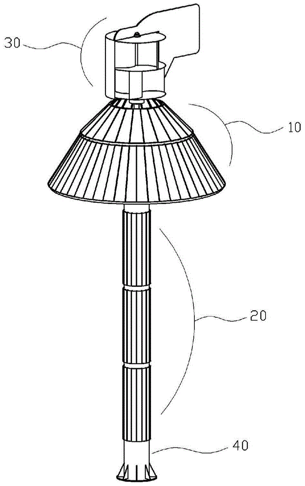
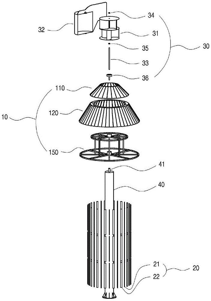
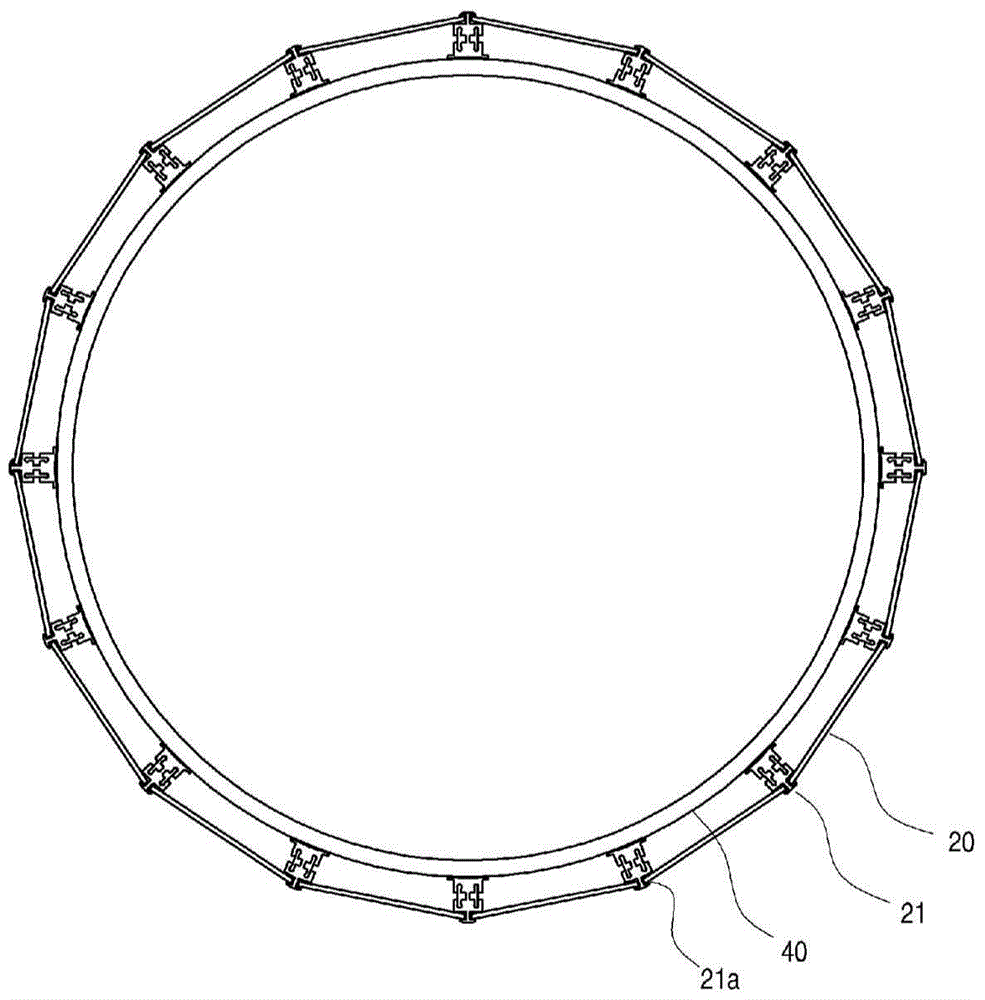
[0045] Hereinafter, the structure of the power generation system integrating circular and polyhedral split sunlight and wind power according to an embodiment of the present invention will be described in more detail with reference to the accompanying drawings.

[0046] figure 1 It is an overall cross-sectional view of a power generation system that integrates circular and polygonal angles to divide sunlight and wind power according to an embodiment of the present invention, figure 2 It is an overall exploded cr...


PUM


Abstract

The invention relates to a power generation system that combines circular and polyhedral angles to divide sunlight and wind power. By increasing the lighting time and dealing with shadows, the efficiency of solar power generation is increased, and the wind density is increased by avoiding the resistance of the wind, thereby increasing The rotational efficiency of the blades, thereby, increases the efficiency of wind power generation.

Description

technical field [0001] This embodiment relates to a power generation system that integrates circular and polygonal angles to divide sunlight and wind power. Background technique [0002] Recently, many products related to sunlight and wind power can be accessed in the world. The solar module converts the light energy into electric energy with the help of sunlight to produce electricity, and the wind generator obtains the rotational force by the wind, and converts the mechanical energy into electric energy to produce electricity, which has the following advantages: no need for conventional power supply Other electrical engineering, and the product is free from defects and can be used semi-permanently. [0003] Figure 11 It is a schematic diagram of direct solar radiation daylighting of a flat-panel solar module in the prior art. [0004] refer to Figure 11 , the existing solar modules are all flat-panel, thus, the flat-panel solar modules have the following disadvantages:...

Claims


Application Information

Patent Timeline
Patent Type & Authority Patents(China)
IPC IPC(8): F03D9/25H01L31/042
CPCF03D9/007H02S10/10H02S10/12H02S30/10Y02E10/50Y02E10/72F03D9/00
Inventor 吴明空
Owner 吴明空
Learn More