Coded aperture beam analysis method and apparatus

A technology of equipment and codewords, applied in the field of coded aperture beam analysis and equipment, can solve the problems of high cost and high power dissipation, long information acquisition time, etc.

Inactive Publication Date: 2014-08-27
HRL LAB
View PDF8 Cites 16 Cited by
  • Summary
  • Abstract
  • Description
  • Claims
  • Application Information

AI Technical Summary

Problems solved by technology

Traditional phased array radar antennas contain a large number of microwave electronics (e.g., multi-bit phase shifters and variable gain amplifiers) at each antenna element, resulting in very high cost and high power dissipation
In addition, conventional phased arrays must sequentially obtain range and Doppler estimates for each beam position, resulting in long information acquisition times for high-gain beams covering a wide field of view

Method used


Image

  • Coded aperture beam analysis method and apparatus
  • Coded aperture beam analysis method and apparatus
  • Coded aperture beam analysis method and apparatus

Examples


Embodiment Construction

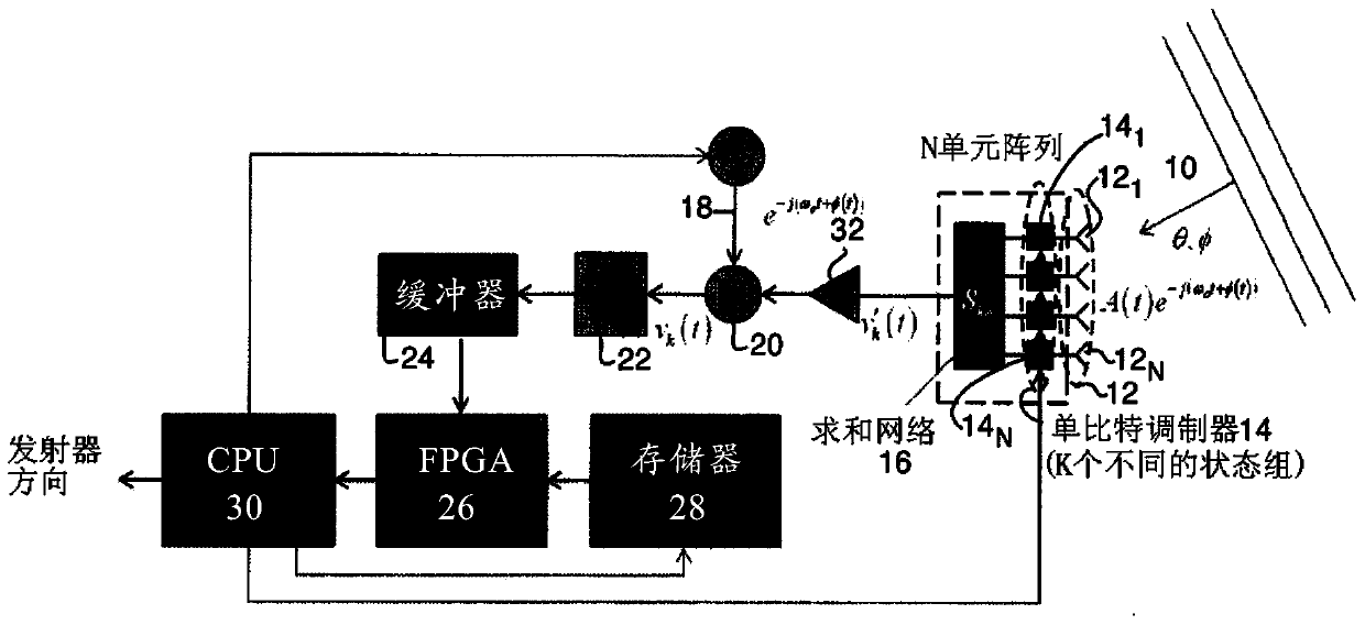
[0034] The coded aperture beamforming technique disclosed herein can be applied in many ways, including radio direction finding and radar (where repetitive signals occur). One embodiment of radio direction finding using aperture beamforming techniques is first described, followed by several embodiments of radar using aperture beamforming techniques.

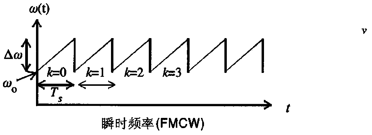
[0035] The "repeating" signal f(t) has a periodicity in time and thus satisfies f(T)=f(t+T), where T is the repetition period. Although this definition applies strictly only to signals of infinite duration (which does not occur in practice), the term "repetitive" is commonly used to describe signals for which the above conditions hold for finite time period, but with significant duration for the system under consideration. Repetitive signals may include pulsed radar waveforms, carrier waves of many communication signals (eg, AM and / or FM radio), synchronization signals transmitted through communication systems, all of which exhi...


PUM


Abstract

A method and apparatus for determining the range, radial velocity, and bearing angles of scattering objects reflecting RF signals or for determining the range, radial velocity, and bearing angles of sources RF signals. An array of antenna elements is utilized, the array of antenna elements each having an associated two state modulator wherein transmitted and / or received energy is phase encoded according to a sequence of multibit codes, the bits of the multibit codes each preferably having two states with approximately a 50% probability for each of the two states occurring within each given multibit code in said sequence of multibit codes, thereby allowing the determination of range, radial velocity, and bearing angles through digital computation after the scattered signals have been received.

Description

[0001] Cross References to Related Applications [0002] This application claims the benefit of US Provisional Patent Application Serial No. 61 / 580,997, filed December 28, 2011, entitled "Coded Aperture Beam Analysis Method and Apparatus," the disclosure of which is incorporated herein by reference. [0003] This application is also a continuation-in-part of US Patent Application Serial No. 13 / 490,607, filed June 7, 2012, entitled "Coded Aperture Beam Analysis Method and Apparatus," the disclosure of which is also incorporated by reference. [0004] This application is related to and claims the benefit of US Patent Application Serial No. 13 / 725,621, entitled "Method and Apparatus for Coded Aperture Beam Analysis," filed December 21, 2012, which is hereby incorporated by reference. technical field [0005] This technique reduces the time required for phased array radars to form range, radial velocity, and azimuth estimates of scattered objects in a wide field of view. Backgro...

Claims


Application Information

Patent Timeline
Patent Type & Authority Applications(China)
IPC IPC(8): G01S7/285G01S7/32H01Q21/00
CPCG01S13/66G01S3/72G01S3/46G01S2013/0245
Inventor 乔纳森·J·林奇
Owner HRL LAB
Why Eureka
Try Eureka