Electromagnetic conduction oil type snow melting vehicle

A snowmobile and electromagnetic technology, which is applied in snow surface cleaning, cleaning methods, construction, etc., can solve the problems of increasing snow removal costs, failure to remove ice, and increased fuel consumption, etc., to achieve convenient and fast snow removal, convenient movement, and high thermal efficiency Effect

Inactive Publication Date: 2014-09-03
SUZHOU CHUANGWEISHENG AUTOMATION SCI & TECH
View PDF5 Cites 0 Cited by
  • Summary
  • Abstract
  • Description
  • Claims
  • Application Information

AI Technical Summary

Problems solved by technology

[0002] In northern cities in winter, due to the influence of snow, the road surface becomes very slippery, which often leads to traffic accidents. At the same time, due to the influence of global warming, the climate in the north has also undergone some changes. It is the alternation of rain and snow, which causes ice and snow on the road surface, causing overpasses, airports, highways, etc. to not operate normally, not only makes the car can only run at a low speed, increases fuel consumption, but also leads to more traffic accidents, which greatly threatens travel For the safety of personnel, the current snow removal methods use snow removal equipment to remove snow or spread snow melting agent to remove snow. However, most of the current snow removal equipment is mechanical, which has the disadvantages of unclean snow removal and inability to remove ice. It takes a lot of manpower and material resources to remove snow shipped away, greatly increasing the cost of snow removal

Method used


Image

  • Electromagnetic conduction oil type snow melting vehicle

Examples


Embodiment Construction

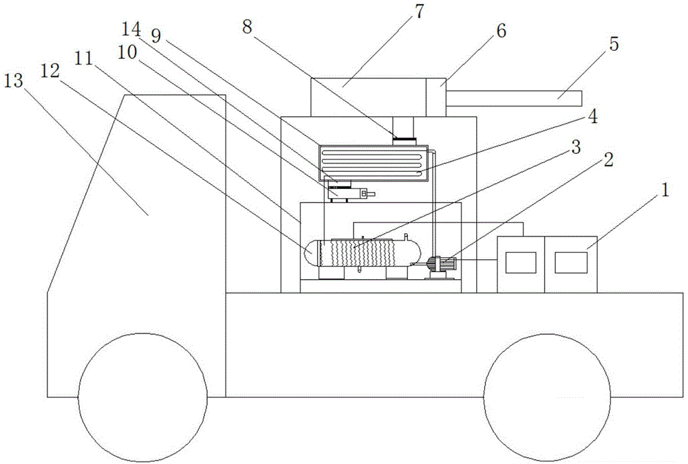
[0010] In order to make the technical means, creative features, goals and effects achieved by the present invention easy to understand, the present invention will be further described below in conjunction with specific illustrations.

[0011] Such as figure 1 Shown is a kind of electromagnetic heat conduction oil type snow melting vehicle, comprising a car body 13, a frame 11 and a generator set 1 are arranged on the car body 13; The thermal oil tank 12 at the lower end of the frame 11 and the heat exchanger 9 arranged at the upper end of the frame 11, several groups of electromagnetic heating coils 3 are arranged in the thermal oil tank 12, and a high temperature circulation is provided on one side of the thermal oil tank 12 Pump 2, the heat exchanger 9 is provided with a heat exchange coil 4, one end of the heat exchange coil 4 is connected to the thermal oil tank 12, and the other end is connected to the thermal oil tank 12 through the high temperature circulation pump 2; ...


PUM


Abstract

The invention provides an electromagnetic conduction oil type snow melting vehicle. The electromagnetic conduction oil type snow melting vehicle comprises a vehicle body; a frame and a generator set are arranged on the vehicle body; a hot air device is arranged on the frame; the hot air device comprises a hot oil tank arranged at the lower end of the frame and a heat exchanger arranged at the upper end of the frame; a plurality of groups of electromagnetic heating coils are arranged in the hot oil tank; a high-temperature circulating pump is arranged at one side of the hot oil tank; a heat exchange coil pipe is arranged in the heat exchanger; one end of the heat exchange coil pipe is connected with the hot oil tank, while the other end of the heat exchange coil pipe is connected with the pipeline of the hot oil tank by use of the high-temperature circulating pump; a hot air outlet and an air suction opening are formed at the two sides, namely the upper and lower ends, of the heat exchanger, respectively; the air suction opening is connected with a filter; the hot air outlet is communicated with an air reservoir arranged at the top of the frame; a supercharger communicated with the air reservoir is arranged at one side of the air reservoir; and the supercharger is connected with a gas ejector pipe. Compared with the prior art, the electromagnetic conduction oil type snow melting vehicle is convenient to move, high in thermal efficiency, convenient and quick for removing snow, and also very simple to operate.

Description

technical field [0001] The invention relates to snow melting equipment, in particular to an electromagnetic heat conduction oil type snow melting vehicle. Background technique [0002] In northern cities in winter, due to the influence of snow, the road surface becomes very slippery, which often leads to traffic accidents. At the same time, due to the influence of global warming, the climate in the north has also undergone some changes. It is the alternation of rain and snow, which causes ice and snow on the road surface, causing overpasses, airports, highways, etc. to not operate normally, not only makes the car can only run at a low speed, increases fuel consumption, but also leads to more traffic accidents, which greatly threatens travel For the safety of personnel, the current snow removal methods use snow removal equipment to remove snow or spread snow melting agent to remove snow. However, most of the current snow removal equipment is mechanical, which has the disadvan...

Claims


Application Information

Patent Timeline
Patent Type & Authority Applications(China)
IPC IPC(8): E01H5/10
Inventor 田银东
Owner SUZHOU CHUANGWEISHENG AUTOMATION SCI & TECH
Why Eureka
Try Eureka