Method for suspending speed tubular column of continuous oil tube

A velocity string and tubing technology, applied in the field of coiled tubing velocity string suspension, can solve problems such as unfavorable well site maintenance and layout, increased maintenance costs, increased supporting requirements, etc., to achieve standardized management and avoid supporting equipment and maintenance costs, the effect of reducing workload

Active Publication Date: 2014-09-03
BEIJING ORION ENERGY TECH DEV
View PDF6 Cites 6 Cited by
  • Summary
  • Abstract
  • Description
  • Claims
  • Application Information

AI Technical Summary

Problems solved by technology

[0017] After hanging the sealed coiled tubing, the production channel through the wellhead hanger is used as the channel for the production of oil and gas wells, and the original production well pattern needs to be changed, which is very unfavorable for the maintenance and layout of the well site;
[0018] Special wellhead hanger equipment (including slips) is added on the ground. This device needs to be placed at the wellhead for a long time, which increases the supporting requirements and increases maintenance costs.

Method used


Image

  • Method for suspending speed tubular column of continuous oil tube
  • Method for suspending speed tubular column of continuous oil tube
  • Method for suspending speed tubular column of continuous oil tube

Examples


Embodiment Construction

[0045] The core of the present invention is to provide a coiled tubing velocity string suspension method, which does not need to change the original production well pattern, thereby reducing the workload and construction cost.

[0046] In order to enable those skilled in the art to better understand the solution of the present invention, the present invention will be further described in detail below in conjunction with the accompanying drawings and specific embodiments.

[0047] Please refer to figure 1 , figure 1 It is a schematic flowchart of a specific embodiment of the suspension method of the coiled tubing velocity string provided by the present invention.

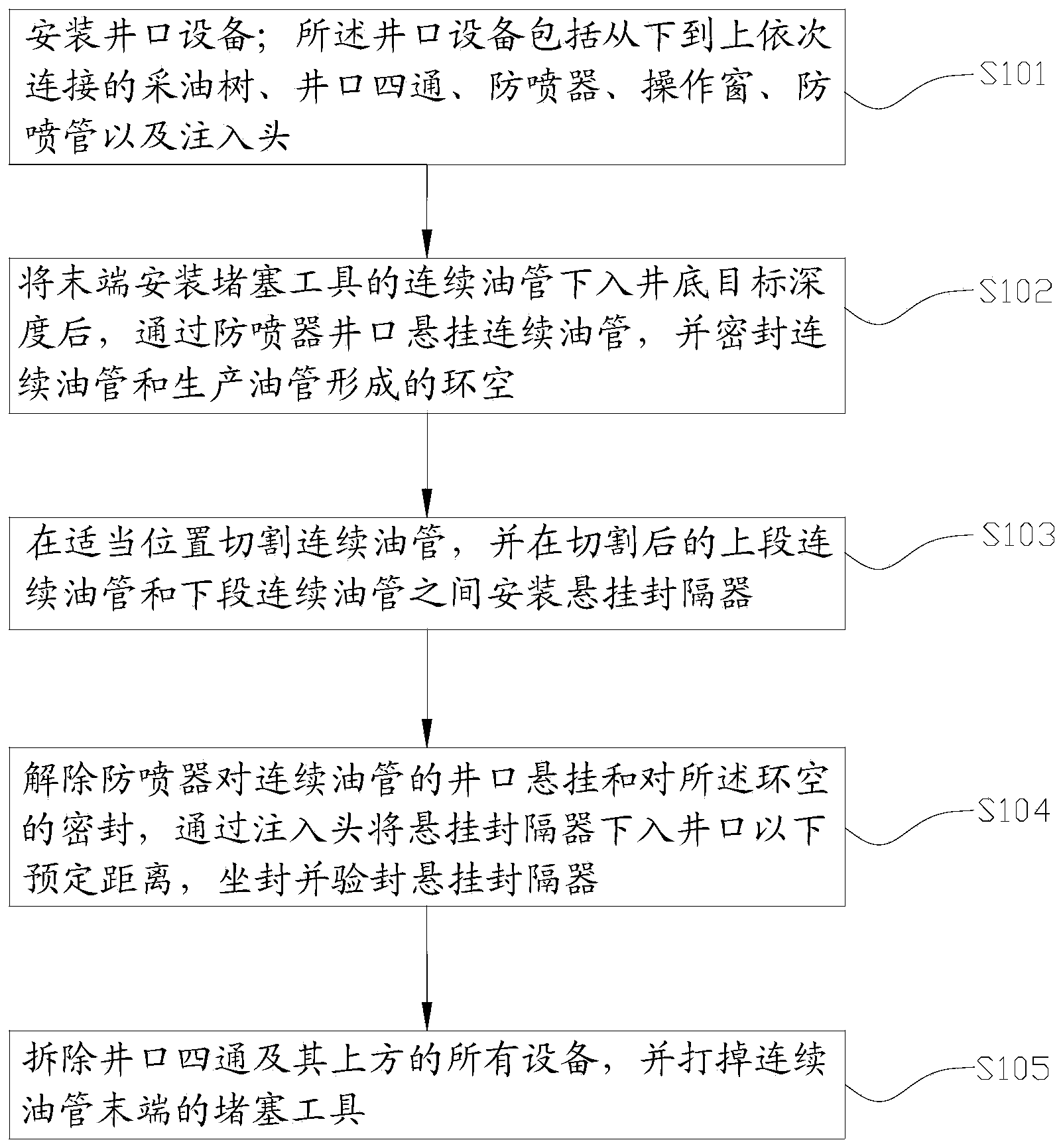
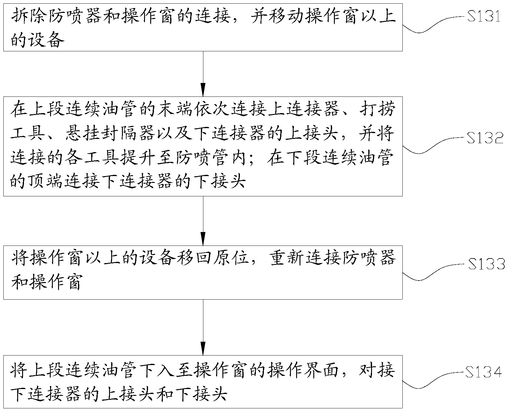
[0048] In this embodiment, the coiled tubing velocity string suspension method provided by the present invention comprises the following steps:

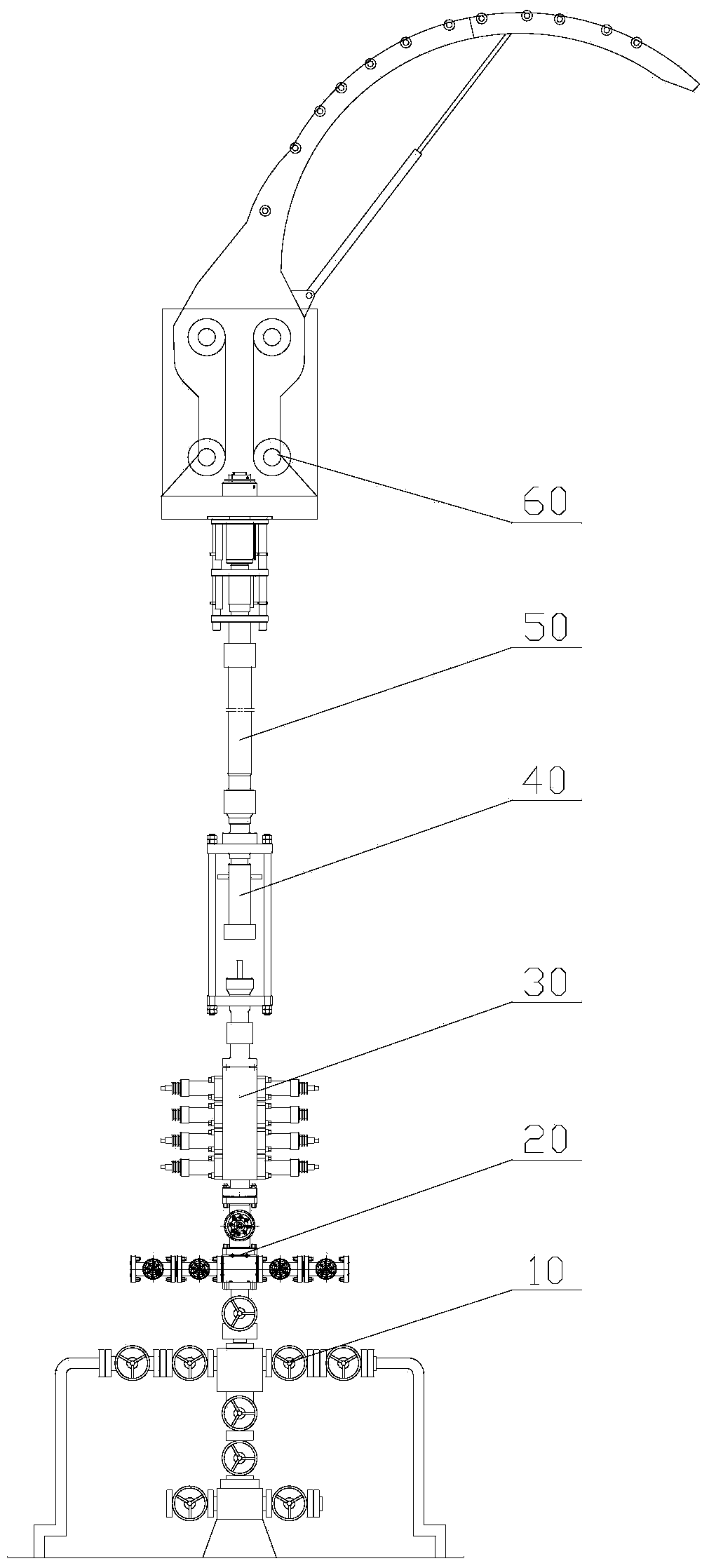
[0049] S101. Install wellhead equipment; the wellhead equipment includes a Christmas tree 10, a wellhead spool 20, a blowout preventer 30, an operation window 40, a blowo...


PUM


Abstract

The invention discloses a method for suspending a speed tubular column of a continuous oil tube. The method includes the following steps that wellhead equipment is installed; the wellhead equipment comprises a Christmas tree, a wellhead cross joint, a blowout preventer, an operating window, a blowout prevention tube and an injection head which are sequentially connected from bottom to top; after the continuous oil tube with a plugging tool at the tail end is placed into a target depth of a downhole, the continuous oil tube is suspended at a wellhead through the blowout preventer, and an annular cavity formed by the continuous oil tube and a production oil tube is sealed; the continuous oil tube is cut at a proper position, and a suspension packer is installed between an upper continuous oil tube section and a lower continuous oil tube section after the continuous oil tube is cut; wellhead suspension for the continuous oil tube through the blowout preventer and sealing for the annular cavity are eliminated, the suspension packer is placed in a preset distance below the wellhead through the injection head, and setting and examining seal are conducted on the suspension packer; the wellhead cross joint and all equipments above the wellhead cross joint are detached, and the plugging tool is knocked off. According to the method, an original producing well pattern does not need to be changed, workloads are relieved, and construction cost is reduced.

Description

technical field [0001] The invention relates to the technical field of oil and gas production, in particular to a method for suspending a coiled tubing velocity string. Background technique [0002] In the process of gas reservoir development, in the middle and later stages of production of gas wells, the back pressure of the bottom hole fluid column continues to increase due to reasons such as gas reservoir pressure drop, edge and bottom water intrusion, gas flow rate drop, bottom hole liquid accumulation, and liquid production increase. , leading to an increase in bottomhole flow pressure, a decrease in production pressure difference, a sharp drop in production, and even shutdown in severe cases. In order to effectively remove bottomhole fluid and maintain normal production of gas wells, the current common method is to use coiled tubing as a velocity string to complete the well. [0003] The diameter of the coiled tubing is much smaller than that of the normal production ...

Claims


Application Information

Patent Timeline
Patent Type & Authority Applications(China)
IPC IPC(8): E21B23/00
Inventor 周聪杨陆武商昌盛崔玉环
Owner BEIJING ORION ENERGY TECH DEV
Why Eureka
Try Eureka