Heat-dissipating device, balance control method and controller

A cooling device and controller technology, applied in pump control, pump devices, components of pumping devices for elastic fluids, etc., can solve the problems of reduced fan life, restricted equipment integration, and reduced fan life

Active Publication Date: 2014-09-03
HUAWEI TECH CO LTD
View PDF6 Cites 5 Cited by
  • Summary
  • Abstract
  • Description
  • Claims
  • Application Information

AI Technical Summary

Problems solved by technology

[0002] With the continuous increase in the integration and power consumption of communication equipment, the demand for fans, the core component of system heat dissipation, is also increasing. Therefore, in order to meet the heat dissipation requirements of communication equipment, the fan pressure and air volume must also meet the corresponding requirements. On the one hand , the performance of the fan can be improved by improving the electrical efficiency of the motor, the aerodynamic efficiency of the blade, and reducing the mechanical loss. On the other hand, increasing the fan speed can significantly improve the performance of the fan. For example, the fan pressure P is proportional to the square of the speed, and the air volume Q is proportional to the speed. Therefore, compared with the improvement of fan efficiency, increasing the fan speed It can improve the fan pressure P and air volume Q. At present, the fan technology in the industry has entered the era of "tens of thousands of speeds", but with the increase of the fan speed, the life of the fan is rapidly reduced. The service life is only 2-3 years at 50 degrees, and it is difficult to meet the 8-10 service life requirements of communication equipment. Therefore, fan performance and service life have become the main bottleneck for improving the performance, integration, reliability and service life of communication equipment.
In addition, as the fan speed increases, vibration and noise will become serious problems, especially for vibration-sensitive storage products, which will seriously restrict the integration of equipment.
[0003] Further analysis, with the improvement of fan performance and speed, as the core component of the fan - the bearing has become the main bottleneck of the speed increase, such as the centrifugal force caused by dynamic imbalance is proportional to the square of the speed, and the wind pressure P is proportional to the square of the speed The relationship between the radial force and the axial force borne by the fan bearing system is proportional to the square of the rotational speed, and the life of the bearing is approximately inversely proportional to the cube of the force. During the use of the fan, due to the inner and outer bearings The wear of the ring will also cause the noise to increase continuously, and finally the fan noise will continue to increase and the life of the fan will be further seriously reduced; therefore, the bearing capacity and life of the bearing system become the key factors restricting the improvement of the fan

Method used


Image

  • Heat-dissipating device, balance control method and controller
  • Heat-dissipating device, balance control method and controller
  • Heat-dissipating device, balance control method and controller

Examples


Embodiment 1

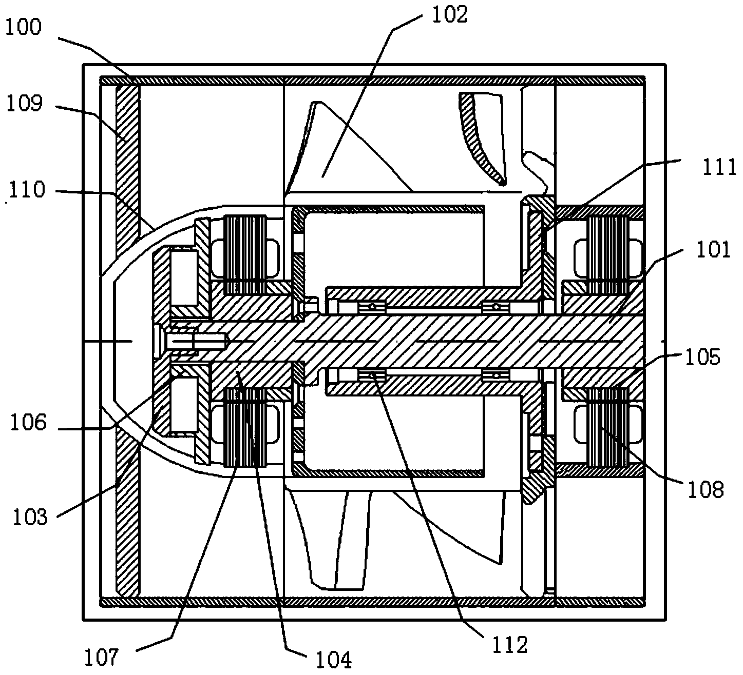
[0074] Embodiment 1. This embodiment provides a cooling device. For the specific structure of the cooling device, please refer to figure 1 as shown, figure 1 It is a schematic cross-sectional top view of a preferred embodiment of the heat dissipation device provided by the embodiment of the present invention.

[0075] Depend on figure 1 It can be seen that the cooling device includes a fan housing 100;

[0076] A driving device (not shown in the figure) is fixedly arranged in the fan casing 100;

[0077] Inside the fan casing 100, a motor shaft 101 is connected to the driving device, that is, the motor shaft 101 can rotate under the power supply of the driving device.

[0078] Wherein, the specific structure of the driving device is an existing technology, which is not limited in this embodiment, as long as the motor shaft 101 can be rotated by the driving device.

[0079] Connected with the motor main shaft 101, there are a plurality of rotors fixedly provided with fan bl...

Embodiment 2

[0106] Embodiment 2. In this embodiment, the specific structure of the heat dissipation device is further described in detail;

[0107] Please continue to see figure 1 As shown, the inside of the fan casing 100 of the heat dissipation device is also fixedly provided with a fan vane 109, which is used as a main load-bearing component in the fan casing 100, which can carry the motor shaft 101 and the rotor 103, The rotor 104 and the rotor 105.

[0108] The fan vane 109 is also used to form an air flow channel inside the fan housing 100 , that is, the fan vane 109 and the fan housing 100 are fixedly provided with a shroud 110 .

[0109] That is, the wind deflector 110 is provided with an accommodating groove, and one end of the motor spindle 101 can be inserted into the accommodating groove of the wind deflector 110 with a gap.

[0110] The wind deflector 110 is fixed in the fan housing 100 through the fan vanes 109 .

[0111] The flow direction of the specific cooling air is:...

Embodiment 3

[0144] Embodiment 3, the heat dissipation device provided by this embodiment can effectively protect the motor shaft and rotor when the motor shaft is powered off, so that the rotor and the magnetic bearing will not collide;

[0145] Please continue to see figure 1 as shown, figure 1 The heat dissipation device shown further includes a motor base 111 , and the motor main shaft 101 is fixedly arranged inside the fan housing 100 through the motor base 111 .

[0146] As long as the motor base 111 is sleeved on the motor main shaft 101 without the axial magnetic bearing and the radial magnetic bearing being sleeved therein, it is acceptable.

[0147] And the motor shaft 101 is in clearance fit with the through hole of the motor base 111 .

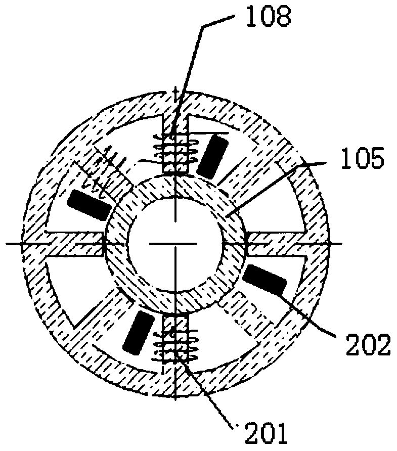
[0148] by figure 1 As shown as an example, the motor base 111 can be sleeved on the motor shaft 101 between the first radial magnetic bearing and the second radial magnetic bearing.

[0149] For the specific arrangement of the first radial ...


PUM


Abstract

The embodiment of the invention provides a heat-dissipating device, a balance control method and a controller. The heat-dissipating device generates axial magnetic force in the axial direction of a main shaft of a motor when an axial magnetic bearing winding of an axial magnetic bearing is powered on and the heat-dissipating device generates radial magnetic force in the radial direction of the main shaft of the motor when a radial magnetic bearing winding of a radial magnetic bearing is powered on, so that the main shaft of the motor is supported by the axial magnetic bearing and the radial magnetic bearing in a suspended mode through the axial magnetic force and the radial magnetic force and the main shaft of the motor is located in the center of the position. The main shaft of the motor is controlled to move to the center of the position so that the main shaft of the motor can be prevented from making mechanical contact with the axial magnetic bearing and the radial magnetic bearing and mechanical abrasion to the main shaft of the motor, the axial magnetic bearing and the radial magnetic bearing can be avoided, and therefore abrasion to the main shaft of the motor, the axial magnetic bearing and the radial magnetic bearing can be effectively relieved and the service life of the heat-dissipating device is effectively prolonged.

Description

technical field [0001] The invention relates to the field of heat dissipation of communication equipment, in particular to a heat dissipation device, a balance control method and a controller. Background technique [0002] With the continuous increase in the integration and power consumption of communication equipment, the demand for fans, the core component of system heat dissipation, is also increasing. Therefore, in order to meet the heat dissipation requirements of communication equipment, the fan pressure and air volume must also meet the corresponding requirements. On the one hand , the performance of the fan can be improved by improving the electrical efficiency of the motor, the aerodynamic efficiency of the blade, and reducing the mechanical loss. On the other hand, increasing the fan speed can significantly improve the performance of the fan. For example, the fan pressure P is proportional to the square of the speed, and the air volume Q is proportional to the spee...

Claims


Application Information

Patent Timeline
Patent Type & Authority Applications(China)
IPC IPC(8): F04D25/08F04D27/00F04D29/66F04D29/058
Inventor 杨成鹏王冬立晁汐
Owner HUAWEI TECH CO LTD
Why Eureka
Try Eureka