A pressure-holding hydraulic system with multi-stage braking function

A hydraulic system and two-stage braking technology, which is applied in the field of pressure-holding hydraulic systems and hydraulic pressure-holding devices, can solve the problems that the pressure-holding hydraulic device cannot realize multi-stage braking operation and the safety hazards of the pressure-holding hydraulic device, and achieve Compact structure, extended oil change interval, and less heat generation

Active Publication Date: 2017-01-18
SHANDONG KEDA ELECTROMECHANICAL TECH CO LTD
View PDF6 Cites 0 Cited by
  • Summary
  • Abstract
  • Description
  • Claims
  • Application Information

AI Technical Summary

Problems solved by technology

[0003] The existing pressure-holding hydraulic device cannot realize multi-stage braking operation, so in the case of overspeed, power failure or other critical situations, it cannot perform the function of point brake deceleration or emergency braking. Therefore, the existing pressure-holding hydraulic device has a greater safety Hidden danger

Method used


Image

  • A pressure-holding hydraulic system with multi-stage braking function
  • A pressure-holding hydraulic system with multi-stage braking function
  • A pressure-holding hydraulic system with multi-stage braking function

Examples


Embodiment Construction

[0023] The following are specific embodiments of the present invention and in conjunction with the accompanying drawings, the technical solutions of the present invention are further described, but the present invention is not limited to these embodiments.

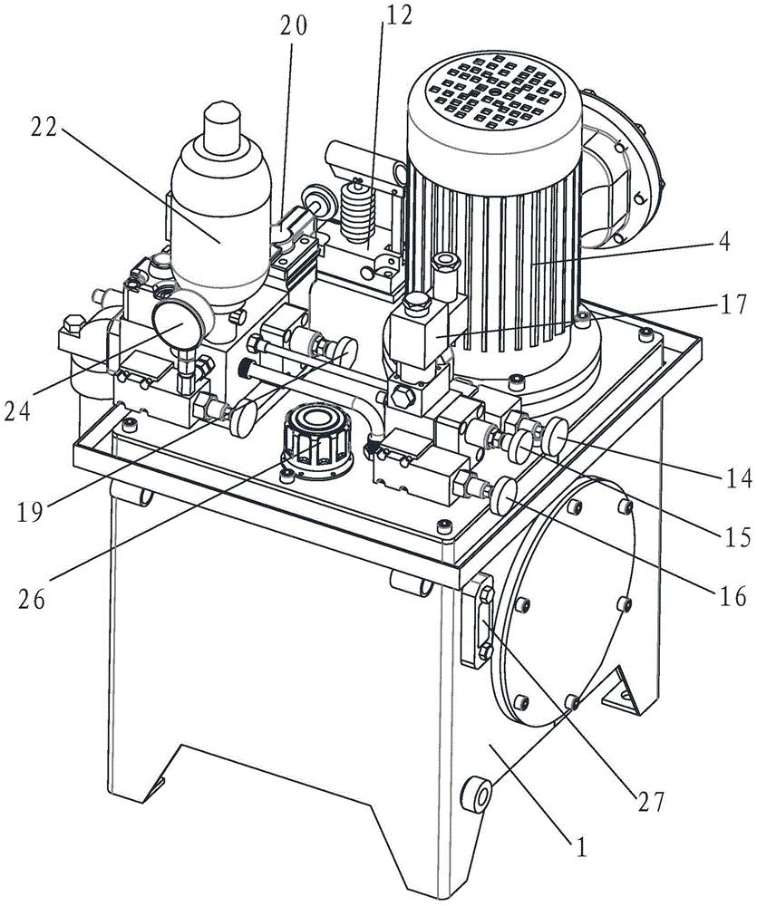
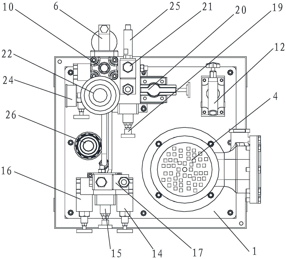
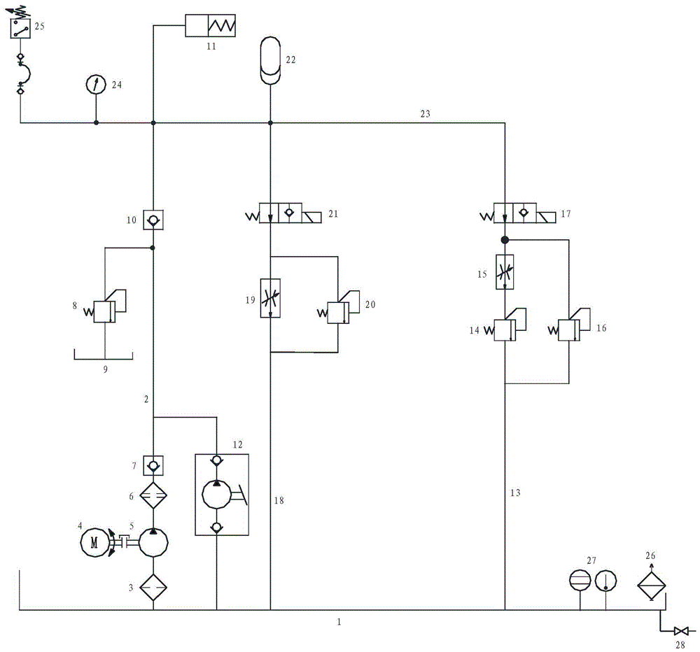
[0024] Such as figure 1 , 2 As shown in and 3, the pressure maintaining hydraulic system with multi-stage braking function includes a fuel tank 1, which is connected with an oil supply oil circuit 2, a primary brake oil circuit 13 and a secondary brake oil circuit 18.

[0025] Oil suction filter 3, gear pump 5, high pressure filter 6, first one-way valve 7, second one-way valve 10 and oil cylinder 11 are connected in series on oil supply circuit 2, wherein gear pump 5 is connected by motor 4 . The first one-way valve 7 is a pipe-type one-way valve; the second one-way valve 10 is a right-angle one-way valve.

[0026] A manual pump 12 is also connected to the oil supply circuit 2 , and the manual pump 12 is connected in p...


PUM


Abstract

The invention provides a pressure-maintaining hydraulic system with the multistage braking function. The pressure-maintaining hydraulic system solves the problem that an existing pressure-maintaining hydraulic device does not have the multistage braking function, and comprises an oil tank. An oil supply oil way, a first-stage braking oil way and a second-stage braking oil way are connected to the oil tank. A sucked oil filter, a gear pump, a high-pressure filter, a first one-way valve, a second one-way valve and an oil cylinder are sequentially connected to the oil supply oil way in series. The first-stage braking oil way is divided into two parallel branches. A first overflow valve and a first throttling valve are connected to one of the two parallel branches in series. A second overflow valve is connected to the other one of the two parallel branches in series. The two parallel branches are joined to be connected with a first explosive-proof reversing ball valve in series. The second-stage braking oil way is divided into two parallel branches. A second throttling valve is connected to one of the two parallel branches in series. A third overflow valve is connected to the other one of the two parallel branches in series. The two parallel branches are joined to be sequentially connected with a second explosive-proof reversing ball valve and an energy accumulator in series. The pressure-maintaining hydraulic system has the multistage braking function, the inching-braking speed reduction braking function and the emergency braking function.

Description

technical field [0001] The invention belongs to the technical field of hydraulic equipment, and relates to a hydraulic pressure maintaining device, in particular to a pressure maintaining hydraulic system with multi-stage braking function. Background technique [0002] The function of the hydraulic system is to increase the force by changing the pressure. A complete hydraulic system consists of five parts, namely power components, actuators, control components, auxiliary components (accessories) and hydraulic oil. The quality of a hydraulic system depends on the rationality of system design, the performance of system components, the pollution prevention and treatment of the system, and the last point is particularly important. [0003] The existing pressure-holding hydraulic device cannot realize multi-stage braking operation, so in the case of overspeed, power failure or other critical situations, it cannot perform the function of point brake deceleration or emergency brak...

Claims


Application Information

Patent Timeline
Patent Type & Authority Patents(China)
IPC IPC(8): F15B11/17F15B1/02
Inventor 李国清成祥宁周生朋吴广清王希凤
Owner SHANDONG KEDA ELECTROMECHANICAL TECH CO LTD
Why Eureka
Try Eureka