Engine, flameholder and concave cavity design method of flameholder

A technology of flame stabilizer and design method, which is applied in the design field of engine, flame stabilizer and its concave cavity, and can solve problems such as narrow application range

Active Publication Date: 2014-09-03
NAT UNIV OF DEFENSE TECH
View PDF3 Cites 5 Cited by
  • Summary
  • Abstract
  • Description
  • Claims
  • Application Information

AI Technical Summary

Problems solved by technology

[0008] The present invention aims to provide a design method for an engine, a flame stabilizer and its cavity, so as to solve the pr

Method used


Image

  • Engine, flameholder and concave cavity design method of flameholder
  • Engine, flameholder and concave cavity design method of flameholder
  • Engine, flameholder and concave cavity design method of flameholder

Examples


Embodiment Construction

[0032] The embodiments of the present invention will be described in detail below with reference to the accompanying drawings, but the present invention can be implemented in many different ways defined and covered by the claims.

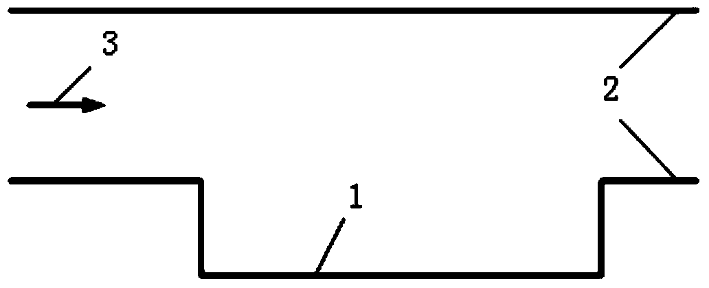
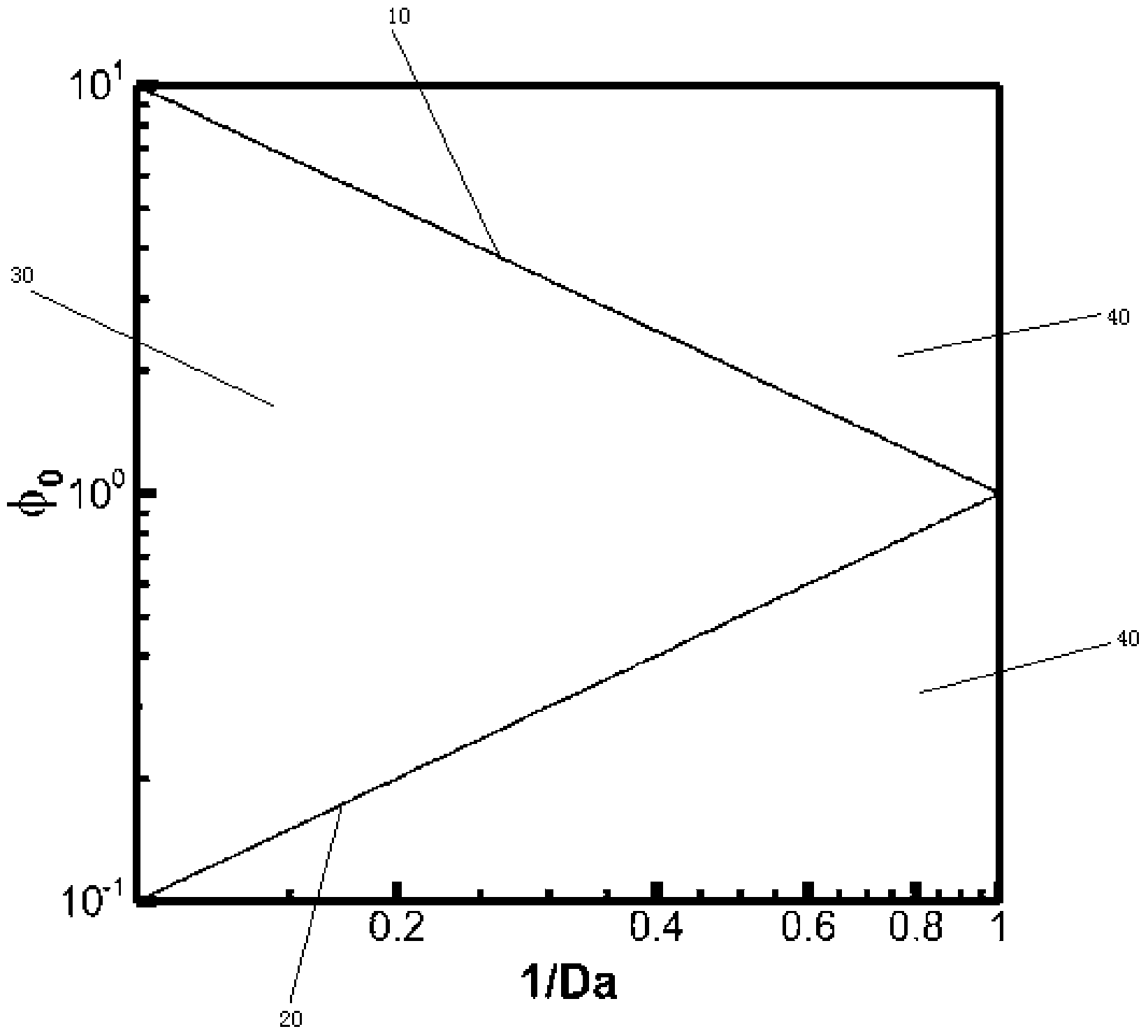
[0033] One aspect of the present invention provides a method for designing a cavity of a flame stabilizer, including: setting the length L of the cavity; determining the effective equivalence ratio φ of the fuel 0 ; When the effective equivalent ratio φ 0 When greater than 1, determine the flame time scale τ in rich combustion f,r , otherwise, determine the flame timescale τ at lean burn f,l ;According to the length value L, the incoming air velocity U and the flame time scale τ at the time of rich combustion f,r or the flame timescale τ at lean burn f,l Determine the Da number of the combustion flow field in the concave cavity, where, or Determined according to the flame blowout criterion (Da, φ 0 ) is located in the flame stable zone, when...


PUM


Abstract

The invention provides an engine, a flameholder and a concave cavity design method of the flameholder. The method includes the steps that the length value L of the concave cavity is set, and the valid equivalent ratio phi0 of fuel is determined; when the valid equivalent ratio phi0 is larger than 1, the flame time scale tau(f,r) in the rich fuel process is determined, and otherwise the flame time scale tau(f,l) in the lean burn process is determined; the Da value of the burn flow field of the concave cavity is determined according to the length value L, the air inflow velocity U , and the flame time scale tau(f,r) in the rich fuel process or the flame time scale tau(f,l) in the lean burn process, wherein the formula is that or , whether the state point (Da, phi0) is located in the flame stable region is determined according to the flame blowoff criterion, when the point (Da, phi0) is located in the flame stable region, the depth D of the concave cavity is determined according to the length depth ratio of the concave cavity, and otherwise the length value L of the concave cavity is reset. The method is simple and easy to implement, the design cycle is short, the universality is good, and the problems that the a method that the concave cavity is designed based on an even stirring reactor model in narrow in practical range and poor in physical basis in the prior art are effectively solved.

Description

technical field [0001] The invention relates to the field of engines, more specifically, to a design method of an engine, a flame stabilizer and a concave cavity thereof. Background technique [0002] Hypersonic aircraft is a strategic high-tech that can achieve high-speed defense penetration, 2-hour global reach, and low-cost space entry. Its development will change the shape of future warfare. pose a new threat to our national security. [0003] As the best alternative power plant for hypersonic air-breathing flight, the scramjet has become a research hotspot in various aerospace powers. As the core component of the scramjet engine, the performance of the supersonic combustion chamber directly determines the success or failure of the entire engine development. Due to the high inflow velocity and short residence time of scramjet, the successful design of supersonic combustor must rely on reliable flame stabilization technology. The method of using wall cavity can effecti...

Claims


Application Information

Patent Timeline
IPC IPC(8): F23R3/18
Inventor 孙明波杨揖心汪洪波梁剑寒
Owner NAT UNIV OF DEFENSE TECH
Why Eureka
Try Eureka