Capacitance test circuit and test method under DC bias condition

A technology of capacitance testing and DC stabilized power supply, which is applied in the direction of measuring resistance/reactance/impedance, measuring devices, and measuring electrical variables, etc. It can solve the problems of inaccurate description of sine wave characteristics, low test frequency, and low instrument life. The effect of eliminating shock, high test frequency and accurate value

Inactive Publication Date: 2014-09-03
NANJING UNIV OF AERONAUTICS & ASTRONAUTICS
View PDF5 Cites 7 Cited by
  • Summary
  • Abstract
  • Description
  • Claims
  • Application Information

AI Technical Summary

Problems solved by technology

In the process of screening the materials, it is necessary to test the electromagnetic characteristics of the materials in the power electronics application environment, including the performance test under the electric field. The existing test methods are as follows: Use an impedance test instrument with a DC bias power supply (such as LCR impedance test instrument) for direct measurement, this method can be used for small signal test under low DC bias, but its DC bias voltage usually does not exceed 100V; series bridge test method, can be used for small signal test under DC bias Signal test,

Method used


Image

  • Capacitance test circuit and test method under DC bias condition
  • Capacitance test circuit and test method under DC bias condition
  • Capacitance test circuit and test method under DC bias condition

Examples


Embodiment Construction

[0022] Embodiments of the present invention will be described below in conjunction with the accompanying drawings.

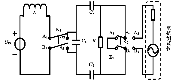
[0023] Such as figure 1 As shown, the present invention has designed a capacitance test circuit under DC bias voltage, including: DC stabilized power supply U DC , inductance L, switch K 1 , the first capacitance C a and a second capacitor C b , impedance tester, two-way switch K 2 , where the DC regulated power supply U DC The positive end of the inductor is connected to the inductor L, and the inductor L is connected to the switch K 1 terminal connection, toggle switch K 1 The other terminal is connected to the capacitance C to be measured x One end of the measured capacitance C x The other end is connected to the DC regulated power supply U DC The negative terminal of the DC regulated power supply U DC After being connected in series with the inductance L, through the switching switch K 1 and the capacitance under test C x connected; the first cap...


PUM


Abstract

The invention discloses capacitance test circuit and test method under a DC bias condition. The circuit comprises a DC voltage stabilizing power source, an inductor, a diverter switch, a first capacitor, a second capacitor, an impedance tester and a bidirectional diverter switch. The DC voltage stabilizing power source and the inductor are connected in series and then are connected with a capacitor to be tested through the diverter switch; the first capacitor and the second capacitor are connected with the two ends of the capacitor to be tested, and the impedance tester is connected between the first capacitor and the second capacitor through the bidirectional diverter switch. The method comprises: switching on the diverter switch, connecting the bidirectional diverter switch to one end of the second capacitor, and charging the capacitor to a stable value; and then connecting the bidirectional diverter switch to the impedance tester, switching to an impedance test state, adjusting the impedance tester to obtain impedance, and then calculating to obtain the impedance of the capacitor to be tested. According to the invention, a charging process and an impedance test process can be switched, the impedance characteristics with in a wide DC bias scope and a wide frequency scope can be measured, and the impact caused by charging and discharging currents of the capacitor to the impedance tester is eliminated.

Description

technical field [0001] The invention relates to a capacitance test circuit and a test method under DC bias voltage, belonging to the technical field of electronic test circuits. Background technique [0002] At present, integrated EMI filters such as planar type, flexible PCB structure type, and busbar type suitable for power electronics applications have been extensively studied. In the integrated EMI filter, the capacitor is an important part, and the high dielectric constant material is the basic material for making such a capacitor. In the process of screening the materials, it is necessary to test the electromagnetic characteristics of the materials in the power electronics application environment, including the performance test under the electric field. The existing test methods are as follows: Use an impedance test instrument with a DC bias power supply (such as LCR impedance test instrument) for direct measurement, this method can be used for small signal test under...

Claims


Application Information

Patent Timeline
IPC IPC(8): G01R27/26
Inventor 王世山王文涛周峰
Owner NANJING UNIV OF AERONAUTICS & ASTRONAUTICS
Why Eureka
Try Eureka