

A measuring system and method for permanent magnet eddy current loss
A technology of eddy current loss and measurement system, which is applied in the direction of magnetic performance measurement, measuring device, and magnetic variable measurement, and can solve the problems of uneven distribution of eddy current and inability to reflect
- Summary
- Abstract
- Description
- Claims
- Application Information
AI Technical Summary
Problems solved by technology
Method used
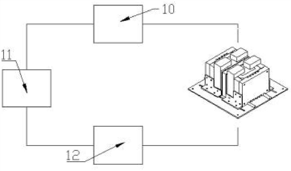
Image

Examples
Embodiment 1
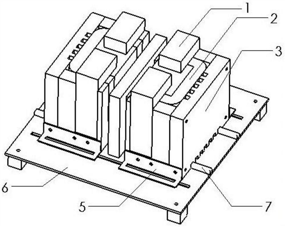
[0041] The number of excitation windings in the measuring system of permanent magnet eddy current loss in this embodiment is four, and the sample to be tested is a cubic NdFeB sample, and the sample size is 10*10*10mm (length*width*height). The excitation frequency is 50Hz.
[0042] Power amplifier model: BROCKHAUS PA50, the voltage signal is amplified 10 times, the input voltage peak value is -10V~+10V, and the output voltage peak value is -100V~+100V. The maximum effective value of the output current is 50A.
[0043] Digital signal processing unit model: NI USB-7856R.
[0044] Differential amplifier circuit model: STANFORD RESERCH SYSTEM MODEL SR560 magnification 10 to 50000 times, working frequency, DC to 1MHz.
[0045] Number of turns of excitation winding: 90 turns / piece.
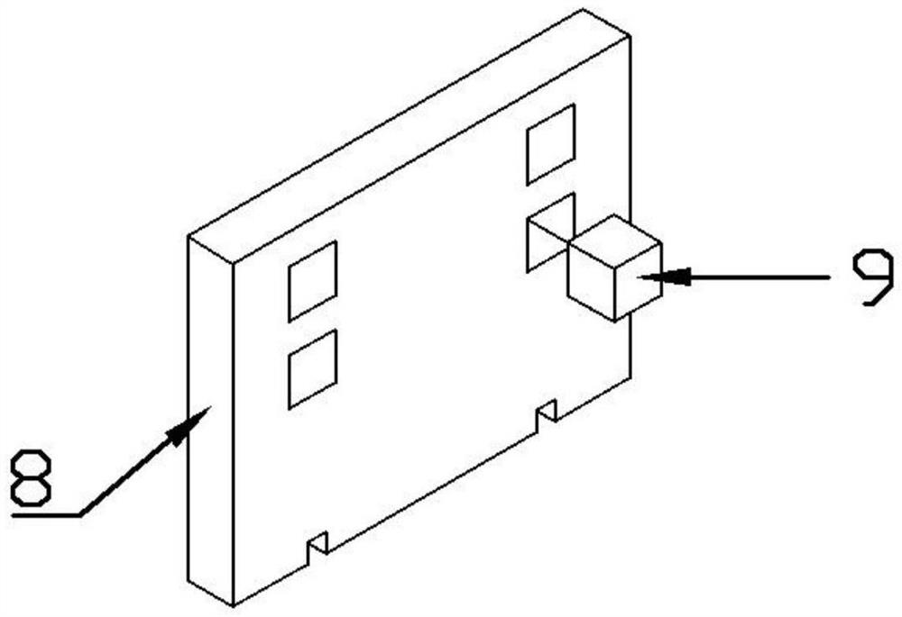
[0046] The maximum external dimension of the magnetic core is 150*100*100mm (length*width*height), and the thickness is 25mm.
PUM
 Abstract
Description
Claims
Application Information