Multichannel optical receiving antenna for visible light communication

An optical receiving antenna, visible light communication technology, applied in optics, optical components, instruments, etc., can solve the problems of increasing the field of view and increasing the volume of the system, difficult to obtain a larger field of view, central energy loss, etc., to save antenna space , Improve portability and minimize the volume occupied

Active Publication Date: 2014-09-03
BEIJING INSTITUTE OF TECHNOLOGYGY
View PDF6 Cites 2 Cited by
  • Summary
  • Abstract
  • Description
  • Claims
  • Application Information

AI Technical Summary

Problems solved by technology

Now the more commonly used receiving optical antennas such as Newton system, Gregory system and Cassegrain system, etc., these systems are not easy to obtain a large field of view, increasing the field of view will increase the volume of the system at the same time, considering the indoor visible light communication The portability of use, the increase of the system size will reduce the practicality; in addition, the above-mentioned system has the problem of central occlusion, and the intensity of the light spot incident on the secondary mirror is generally Gaussian distribution, the existence of the occlusion ratio makes the energy loss of the central part

Method used


Image

  • Multichannel optical receiving antenna for visible light communication
  • Multichannel optical receiving antenna for visible light communication
  • Multichannel optical receiving antenna for visible light communication

Examples


Embodiment Construction

[0032] The present invention will be described in detail below with reference to the drawings and embodiments.

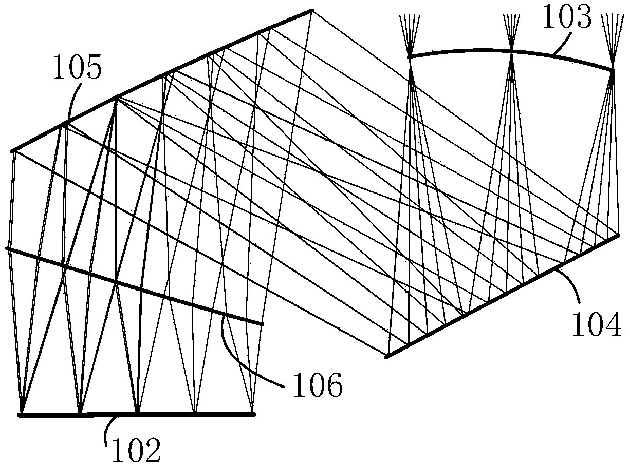
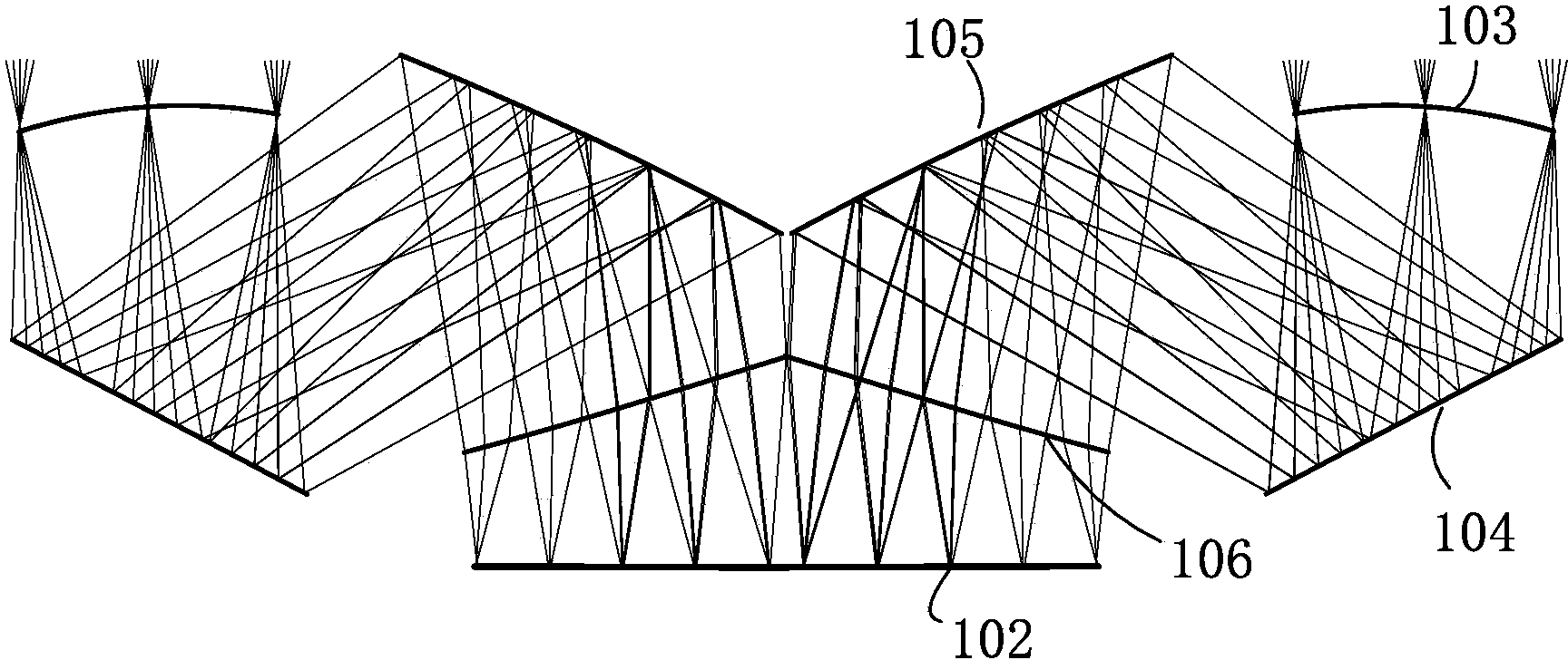
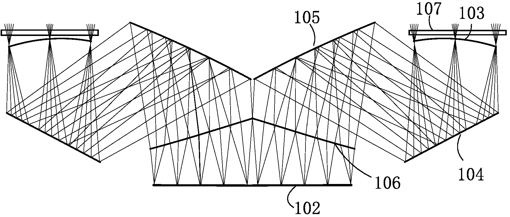
[0033] The present invention provides a multi-channel optical receiving antenna for visible light communication, including more than one off-axis lens system, such as figure 1 As shown, the lens system includes a photodetector 102 and four optical surfaces: a first transmission surface 103, a first reflection surface 104, a second reflection surface 105, and a second transmission surface 106, wherein two reflection surfaces and two transmission surfaces are opposite to each other. Tilt for the reference axis. The first transmission surface 103 is used to receive visible light in the free space, and the first reflection surface 104 is placed in the transmission light path of the first transmission mirror, and reflects the visible light condensed by the first transmission surface 103 to the second reflection surface 105, such as figure 1 As shown, the second reflective su...


PUM


Abstract

The invention provides an optical receiving antenna for visible light communication, which comprises N lens systems. Each lens system comprises a photoelectric detector and four optical surfaces. A first transmission surface receives visible light. A first reflection surface is placed in the transmission optical path of a first transmission lens and reflects visible light which is converged by the first transmission surface to a second reflection surface. After the second reflection surface receives the reflected light of the first reflection surface, the second reflection surface reflects to a second transmission surface. After transmission of the reflected light, the second transmission surface focuses the light to the photoelectric detector on an image surface. Each lens system receives light waves with different wave bands in the visible light. The photoelectric detector in the lens system receives the light wave with a corresponding wave band. The optical receiving antenna of the invention can realize multichannel receiving at the receiving end of the optical antenna, thereby increasing bandwidth. Simultaneously, utilization of a catadioptric off-axis structure reduces system volume and realizes miniaturization of an optical receiving antenna.

Description

Technical field [0001] The invention relates to the field of optical design, in particular to an optical receiving antenna for visible light communication. Background technique [0002] The characteristics of signal light in indoor visible light communication are large coverage area and wide field of view. To ensure the intensity of the received signal light, if the actual physical area of ​​the photodetector is directly increased, the internal noise of the detector will be increased, and at the same time, the response bandwidth of the receiver will be limited due to the increase of the equivalent capacitance. Therefore, an optical receiving system can be placed in front of the detector to increase the equivalent receiving area: the large field of view signal light can be received by the optical receiving system into the detector as much as possible, thereby equivalently expanding the receiving area and receiving field of view. Increase the received optical power. [0003] The re...

Claims


Application Information

Patent Timeline
Patent Type & Authority Applications(China)
IPC IPC(8): G02B17/08H04B10/116
Inventor 程德文张凌云宋维涛王涌天刘越
Owner BEIJING INSTITUTE OF TECHNOLOGYGY
Why Eureka
Try Eureka