Supercharge Your Innovation With Domain-Expert AI Agents!

Novel power transformer with functions of direct current magnetic bias and reactive compensation

A technology for power transformers and DC bias magnetization, applied in reactive power compensation, transformers, reactive power adjustment/elimination/compensation and other directions, which can solve the problems of difficulty in selecting compensation ground poles, reduced compensation current efficiency, and poor power grid short-circuit fault capability. , to solve the problem of DC bias, suppress DC bias, and ensure safe operation.

Inactive Publication Date: 2014-09-03
SHENYANG POLYTECHNIC UNIV
View PDF6 Cites 8 Cited by
  • Summary
  • Abstract
  • Description
  • Claims
  • Application Information

AI Technical Summary

Problems solved by technology

[0009] However, there are certain problems in each method
The small resistance current limiting method cannot completely eliminate the neutral point DC current, and sometimes a resistor with a larger resistance value has to be used, which may affect the insulation strength of the neutral point of the main transformer; although the capacitor DC blocking method can better eliminate the neutral point DC current. DC current, but it affects the effective grounding of the transformer. It has high requirements on the insulation strength of the neutral point of the main transformer, and its ability to deal with short-circuit faults in the power grid is poor; very difficult to choose
And in the long-distance power transmission system, the efficiency of the compensation current will be reduced, the power of the DC generator will be doubled, and the large current entering the ground will also increase the burden on the ground grid, accelerate the corrosion of the ground grid, and the application cost is extremely high; the potential compensation method consumes a lot of power , the device is more expensive, and the selection of the compensation ground pole is also more difficult

Method used


Image

  • Novel power transformer with functions of direct current magnetic bias and reactive compensation

Examples


Embodiment Construction

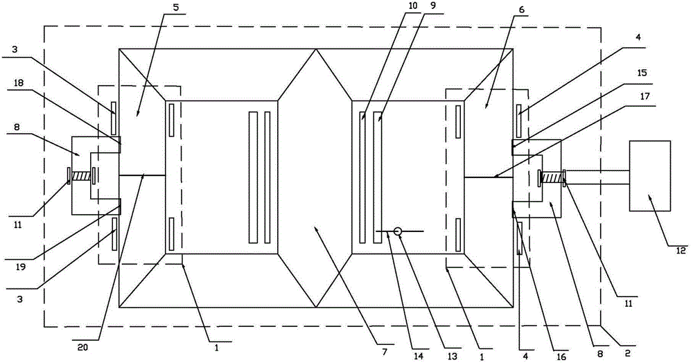
[0022] The present invention is described in detail below in conjunction with accompanying drawing:

[0023]The invention proposes a new type of power transformer with both DC bias and reactive power compensation functions. Through the combination of transformers, reactors and control systems, an energy-saving intelligent power transformer with DC bias compensation and reactive power compensation capabilities is formed. The transformer detects the reactive power status of the power grid and the DC bias magnetism of the transformer through the detection and control system in real time. When the system detects that the transformer needs to adjust the reactive power of the grid and compensate the DC bias The conversion between the magnetic conduction and DC excitation functions completes the "detection, control and elimination" of the transformer's reactive power compensation and DC bias. This new type of transformer integrates a controllable reactor, that is, it has the function...


PUM


Abstract

The invention relates to a novel power transformer with functions of direct current magnetic bias and reactive compensation. The novel power transformer comprises electric reactors and a transformer body, wherein the electric reactors wind transformer side masts, the transformer body comprises an iron core and windings, and the iron core comprises a first side mast, a second side mast, a main core mast and a two-phase magnetic material. By virtue of the special arrangement of the windings, the magnet integration of the electric reactors and the transformer body is realized, and the inductance can be invoked to perform reactive compensation; a current sensor is established to detect bias magnet flux, and the intelligent conversion of a magnetic conduction function and a direct current excitation function of the two-phase magnetic material can be realized through a control device so as to detect, control and eliminate the direct current magnetic bias of the transformer.

Description

technical field [0001] The invention relates to the field of electrical engineering, and specifically refers to a power transformer with intelligent features that integrates a controllable reactor and can realize DC bias compensation and reactive power compensation functions. Background technique [0002] Since the 1970s and 1980s, with the development of ultra-high voltage long-distance transmission systems and the aggravation of the impact of power system load changes, the reactive power consumption in the power grid is increasing day by day. The lack of reactive power is the cause of my country's low power quality and an important factor of waste. Controllable reactors and capacitor banks operate in coordination with each other to adjust reactive power. Therefore, in UHV or EHV, large-capacity power grids, a certain reactive power compensation device is installed to control the reactive power flow and stabilize the operating voltage of the power grid. A large number of t...

Claims


Application Information

Patent Timeline
IPC IPC(8): H01F30/06H01F38/00H01F27/40H01F27/30H01F27/24H02J3/18
CPCY02E40/30
Inventor 白保东陈志伟胡召富于江华赵晓旋王禹
Owner SHENYANG POLYTECHNIC UNIV
Features
  • R&D
  • Intellectual Property
  • Life Sciences
  • Materials
  • Tech Scout
  • Unparalleled Data Quality
  • Higher Quality Content
  • 60% Fewer Hallucinations
Learn More