
Electronic line protection apparatus

A protection device and electronic circuit technology, applied in the direction of overcurrent protection, measuring devices, and measuring electrical variables, etc., can solve problems such as load effect and line loss, low production efficiency of protection components, and scattered overcurrent protection devices , to achieve excellent resistance value and resistance reproducibility, low production efficiency, and large current controllable range

Inactive Publication Date: 2014-09-03
TONGCHENG SINBON ELECTRONICS
View PDF3 Cites 0 Cited by
  • Summary
  • Abstract
  • Description
  • Claims
  • Application Information

AI Technical Summary

Problems solved by technology

[0002] In recent years, high-tech technology has advanced by leaps and bounds, especially in the field of microelectronics-related technology and process. Therefore, electronic products have already penetrated into every family. Two safety problems that often occur in electronic products are over-voltage and over-current conditions. Solve this The two problems are the protection of wider application of electronic products. The patent application number is CN200320113740.3, which solves the problem of over-dispersion of over-current protection devices, thereby increasing the efficiency of space use and reducing assembly costs, but it cannot be integrated with the load circuit Phase isolation will cause load effect and line loss, and the current controllable range is small; the production efficiency of protection components is low, and its resistance value and performance are poor

Method used


Image

  • Electronic line protection apparatus
  • Electronic line protection apparatus

Examples


Embodiment Construction

[0015] The present invention will be further described in detail below with reference to the drawings and specific embodiments.

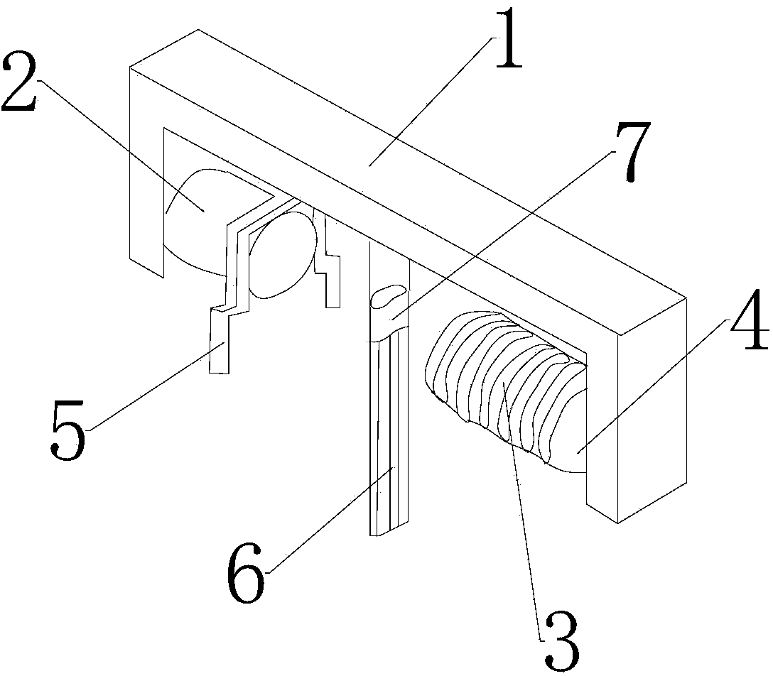
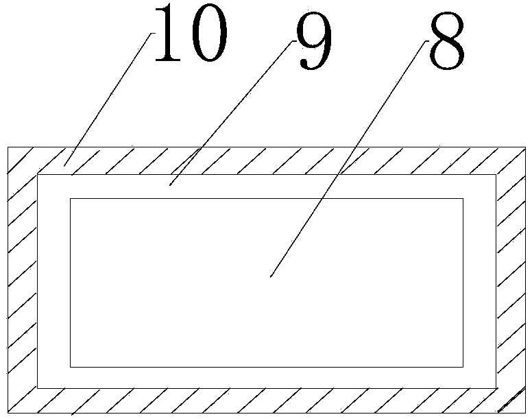
[0016] Such as figure 1 with figure 2 Shown: An electronic circuit protection device includes an iron core 1 and a protection element 6, the iron core 1 is connected to the protection element 6, a first protrusion 2 is connected to one side of the iron core 1, and the iron core 1 The other side of the core 1 is connected to a second convex body 4, the second convex body 4 is connected to the main coil 3, the protection element 6 includes an electrode sheet 8, and the electrode sheet 8 is connected to a composite layer 9, so The composite layer 9 is connected with an adhesive layer 10, the volume resistance of the adhesive layer 10 is 0.01-0.02 ohm / cm, there is a certain distance between the two convex bodies, and the low-voltage drop resistance is achieved through the protection element 6, and It can accurately measure the effect of current value, wi...


PUM


Abstract

The invention discloses an electronic line protection apparatus, and relates to the field of electronics. The apparatus comprises an iron core and a protection element. One side of the iron core is connected with a first convex body, the other side of the iron core is connected with a second convex body, the second convex body is connected with a main coil, the protection element comprises an electrode slice, the electrode slice is connected with a composite layer, the composite layer is connected with an adhesive layer, the volume resistance of the adhesive layer is 0.01-0.02 ohm / cm, and there is a certain distance between the two convex bodies. Besides, through the protection element, low voltage drop resistance is realized, the effect of accurately measuring current values can be realized, no load effects are generated, a line is protected from loss, the current controllable scope is large, a conventional protection element has low production efficiency and poor resistance values and performance, the electrode slice is connected with the composite layer, the composite layer is connected with the adhesive layer, excellent resistance values and resistance reproducibility are exhibited, and at the same time, the preparation efficiency of an overcurrent protection element is high.

Description

Technical field [0001] The invention relates to the field of electronic circuits, in particular to an electronic circuit protection device. Background technique [0002] In recent years, high-tech technology has advanced by leaps and bounds, especially in the field of microelectronics-related technology processes. Therefore, electronic production has already penetrated into every family. The two safety problems that often occur in electronic products are overvoltage and overcurrent conditions. The two problems are that electronic products are guaranteed to be more widely used. The patent application number CN200320113740.3 solves the problem of excessive dispersion of overcurrent protection devices, thereby increasing the efficiency of space use and reducing assembly costs, but it cannot be connected to the load circuit. Phase isolation will cause load effect and line loss, and the current controllable range is small; the production efficiency of the protection element is low,...

Claims


Application Information

Patent Timeline
Patent Type & Authority Applications(China)
IPC IPC(8): H02H3/08G01R19/00
Inventor 赵占兵
Owner TONGCHENG SINBON ELECTRONICS
Learn More