Double-loop power source mutual-throw device

A double-loop, loop voltage technology, applied in the direction of circuit devices, emergency power supply arrangements, electrical components, etc., can solve the problems of load user equipment hazards, long switching time, ignition and arcing, etc., to achieve light weight, avoid short-circuit phenomenon, The effect of quick switching

Inactive Publication Date: 2014-09-03
TIANJIN FUHAIYINYANG ENERGY TECH DEV
View PDF4 Cites 1 Cited by
  • Summary
  • Abstract
  • Description
  • Claims
  • Application Information

AI Technical Summary

Problems solved by technology

However, the switching time between the common circuit and the standing circuit is still long, and circuit oscillation and ignition and arcing are prone to occur, which will bring harm to the load user equipment

Method used


Image

  • Double-loop power source mutual-throw device
  • Double-loop power source mutual-throw device
  • Double-loop power source mutual-throw device

Examples


Embodiment Construction

[0016] The specific implementation, structure, features and effects provided by the present invention will be described in detail below in conjunction with the accompanying drawings and preferred embodiments.

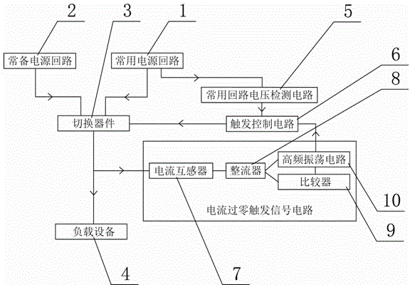
[0017] In the figure: 1. Common power circuit; 2. Standby power circuit; 3. Switching device; 4. Load equipment; 5. Common circuit voltage detection circuit; 6. Trigger control circuit; 7. Current transformer; 8. Rectifier; 9 , Comparator; 10, high-frequency oscillation circuit.

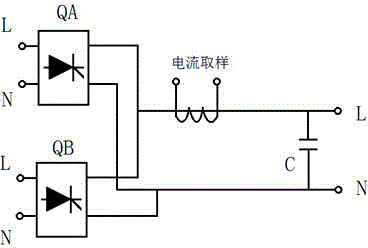
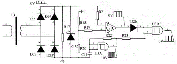
[0018] like Figure 1-4 As shown: the common power circuit 1 and the standing power circuit 2 are respectively connected to the load device 4 through the switching device 3, and the common circuit voltage detection circuit 5 is respectively connected to the common power circuit 1 and the trigger control circuit 6, and the The current zero-crossing trigger signal circuit is located between the common power supply circuit 1 and the load device 4, and is connected to the trigger control circuit ...


PUM


Abstract

The invention provides a double-loop power source mutual-throw device which can be switched rapidly between a common loop and an ever-prepared loop and avoid circuit vibration and arcing. The double-loop power source mutual-throw device comprises a switching component, and the common loop in common use and the loop ever prepared are respectively connected with load equipment through the switching component. The double-loop power source mutual-throw device is characterized by further comprising a common loop voltage detection circuit, a current zero-passing trigger signal circuit and a trigger control circuit. The common loop voltage detection circuit is respectively connected with the common power source loop and the trigger control circuit. The current zero-passing trigger signal circuit is located between the common power source loop and the load equipment and connected with the trigger control circuit connected with the switching component. Switching time of a double-loop power source is shorter than or equal to 5 ms, and normal operation of the load equipment will not be affected. Silicon controlled modules are adopted for the switching component of a main circuit, so that the size of the device is small, the device is light, and the arcing will not exist in the switching process.

Description

technical field [0001] The invention belongs to a dual-circuit power supply automatic conversion device, in particular to a dual-circuit power supply mutual input device. Background technique [0002] In the power distribution lines of the prior art, in order to ensure the quality of power supply and reduce the number of power outages, some highly specialized units such as railways and hospitals have two-way power supply systems. AC contactors, relays or switches switch to the standing power circuit. For example, the Chinese patent with application number 200620168623.0 discloses a fast dual power switcher, which relates to a contact type dual power mutual input device and an AC non-contact switch, and is characterized in that: the switch of the contact type dual power mutual input device (C1 ) and (C2) are respectively connected in parallel non-contact switches (K1) and (K2), the parallel circuit is connected in series with the output circuit, both the contact switch and ...

Claims


Application Information

Patent Timeline
Patent Type & Authority Applications(China)
IPC IPC(8): H02J9/06
CPCY02B70/30Y04S20/20
Inventor 关玉兰
Owner TIANJIN FUHAIYINYANG ENERGY TECH DEV
Why Eureka
Try Eureka