Multifunctional automatic lumbosacral portion concave-traction and arc-shaped-massaging device and using method
An automatic device and multi-functional technology, applied in the field of medical equipment, can solve problems such as short use time and difficulty in developing massage devices
- Summary
- Abstract
- Description
- Claims
- Application Information
AI Technical Summary
Problems solved by technology
Method used
Image
Examples
Embodiment 1
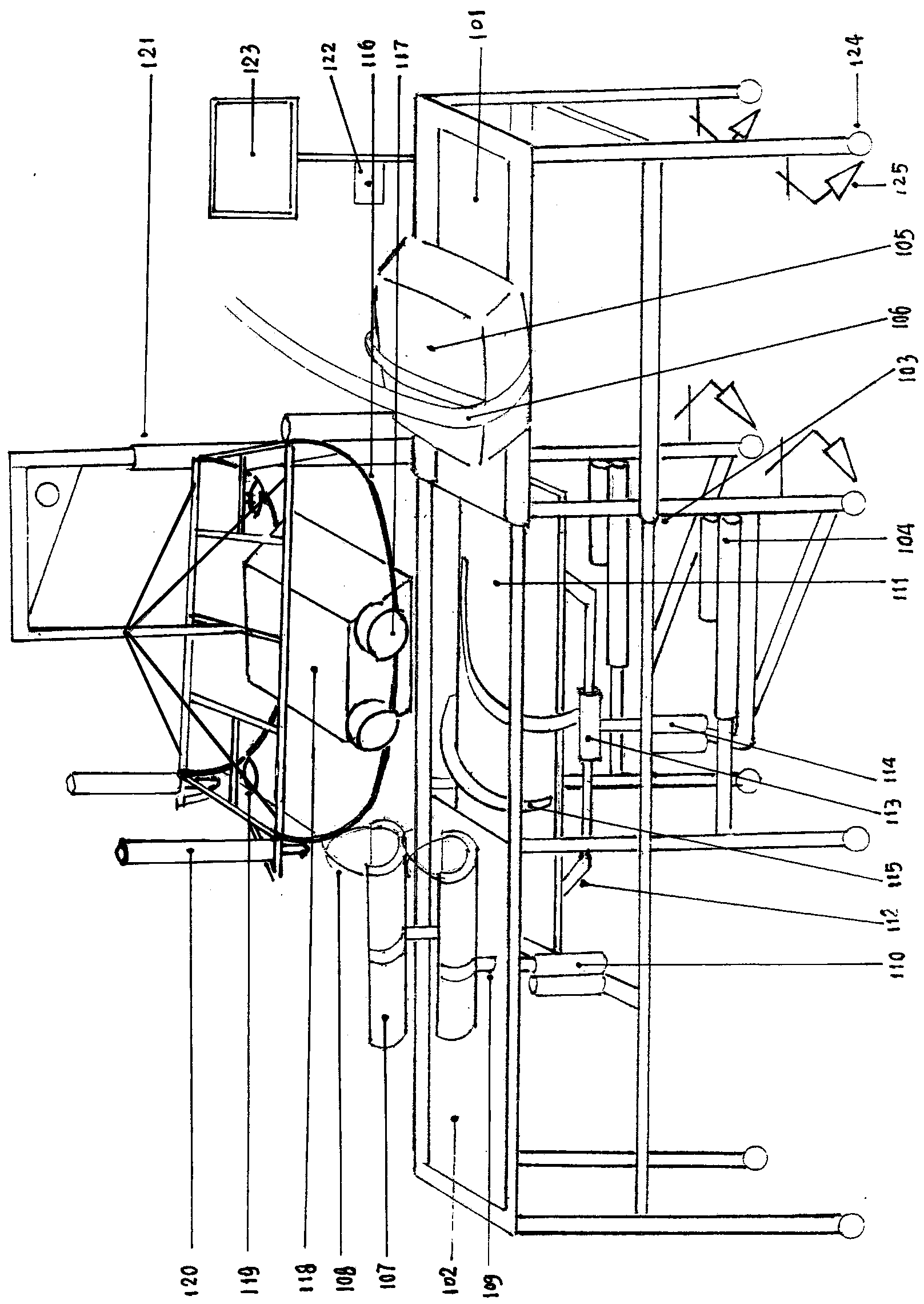
[0035] Embodiment one, such as figure 1 As shown, the main body of the present invention is a semi-convex and semi-concave traction concave structure and a massage device composed of a front bed body (101) and a rear bed body (102) with independent support capabilities. The front and rear bed bodies have four legs. Pulleys (124), the four pulleys of the front bed body are designed with locking fixtures (125), and the connection method between the front bed body and the rear bed body includes at least two metal tubes on the edge of the bed, a large tube sleeve and a small tube through-fitting connection structure (103) , and the length of the small tube interspersed in the large tube is at least 800mm~10000mm, and at least an electric telescopic device (104) for adjusting the distance between the front and rear beds is installed between the front and rear beds. By adjusting the distance between the front and rear beds, at least the front and rear beds can be adjusted The distan...
Embodiment 2
[0048] Embodiment 2, the main structure of embodiment 2 is the same as that of embodiment 1, most of the main structural parts are the same, the difference is:
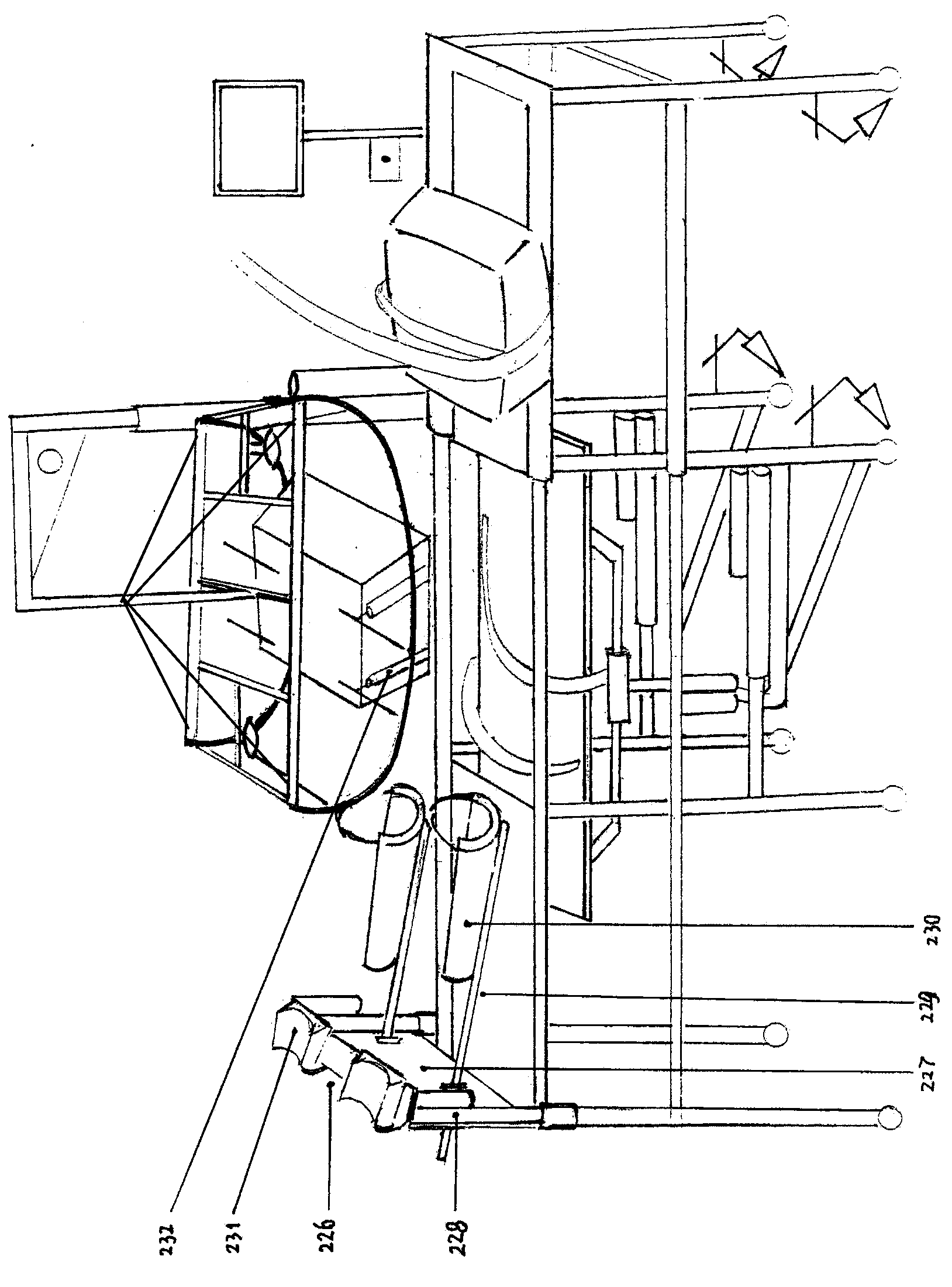
[0049] Such as figure 2 figure 1 As shown, two relatively independent lower limb rests on the left and right can be designed as a door-shaped structure (226). The crossbeam (227), the lower limb support electric telescopic device is installed on the structural member at the foot end of the rear bed body (102) at 0 mm ~ 200 mm, the end of the crossbeam (227) shown at least includes a ""-shaped structure, as shown The width of the structural sheet in the vertical direction of the ""-shaped structure is 50 mm~100 mm (referring to the distance between the upper and lower points), and the width of the structural sheet in the horizontal direction is about three-fifths of the width of the structural sheet in the vertical direction. At least two mounting holes can be drilled on the structural sheet, and at least one end of...
Embodiment 3
[0052] The third embodiment, the third embodiment is an example of temporarily using the traction bed with a semi-convex and semi-concave concave structure as a flat bed.
[0053] Such as figure 1 figure 2 For the semi-convex and semi-concave concave structure traction bed shown, the user needs to temporarily use the flat bed body, and the semi-convex and semi-concave concave structure can be temporarily withdrawn. The withdrawal method includes at least withdrawing the chest support (105) and Place it on the surface of the concave floor (111), adjust the height of the concave floor so that the chest support and the front and rear bed surfaces remain at the same level, and withdraw the left and right relatively independent lower limbs from the pin connection of the telescopic shaft of the electric telescopic device of the lower limb support. Support (107) and / or cancel the gate-shaped structure lower limb support (226) as a whole from the telescopic shaft of the door-shaped ...
PUM
 Abstract
Description
Claims
Application Information
 - R&D
- Intellectual Property
- Life Sciences
- Materials
- Tech Scout
- Unparalleled Data Quality
- Higher Quality Content
- 60% Fewer Hallucinations
Browse by: Latest US Patents, China's latest patents, Technical Efficacy Thesaurus, Application Domain, Technology Topic, Popular Technical Reports.
© 2025 PatSnap. All rights reserved.Legal|Privacy policy|Modern Slavery Act Transparency Statement|Sitemap|About US| Contact US: help@patsnap.com


