Propeller with trailing edge for air jetting

A propeller and trailing edge technology, applied in the field of aviation propulsion, can solve problems such as low efficiency

Active Publication Date: 2014-09-10
NORTHWESTERN POLYTECHNICAL UNIV
View PDF6 Cites 4 Cited by
  • Summary
  • Abstract
  • Description
  • Claims
  • Application Information

AI Technical Summary

Problems solved by technology

The above two modes of rotor wing tip jet flow are only air jets, which do not fundamentally change the flow characterist

Method used


Image

  • Propeller with trailing edge for air jetting
  • Propeller with trailing edge for air jetting
  • Propeller with trailing edge for air jetting

Examples


Embodiment Construction

[0017] This embodiment is a propeller with trailing edge jet.

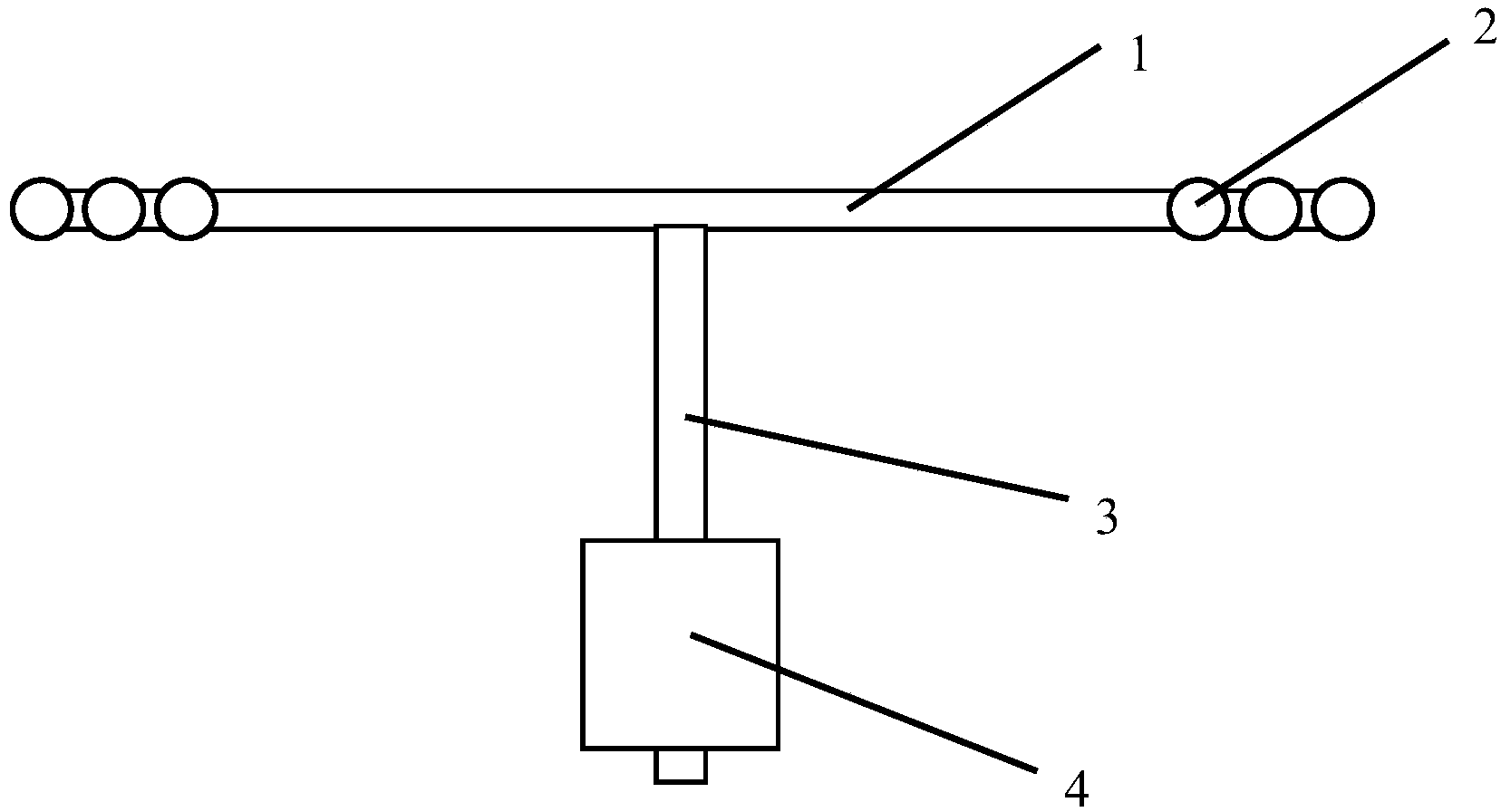
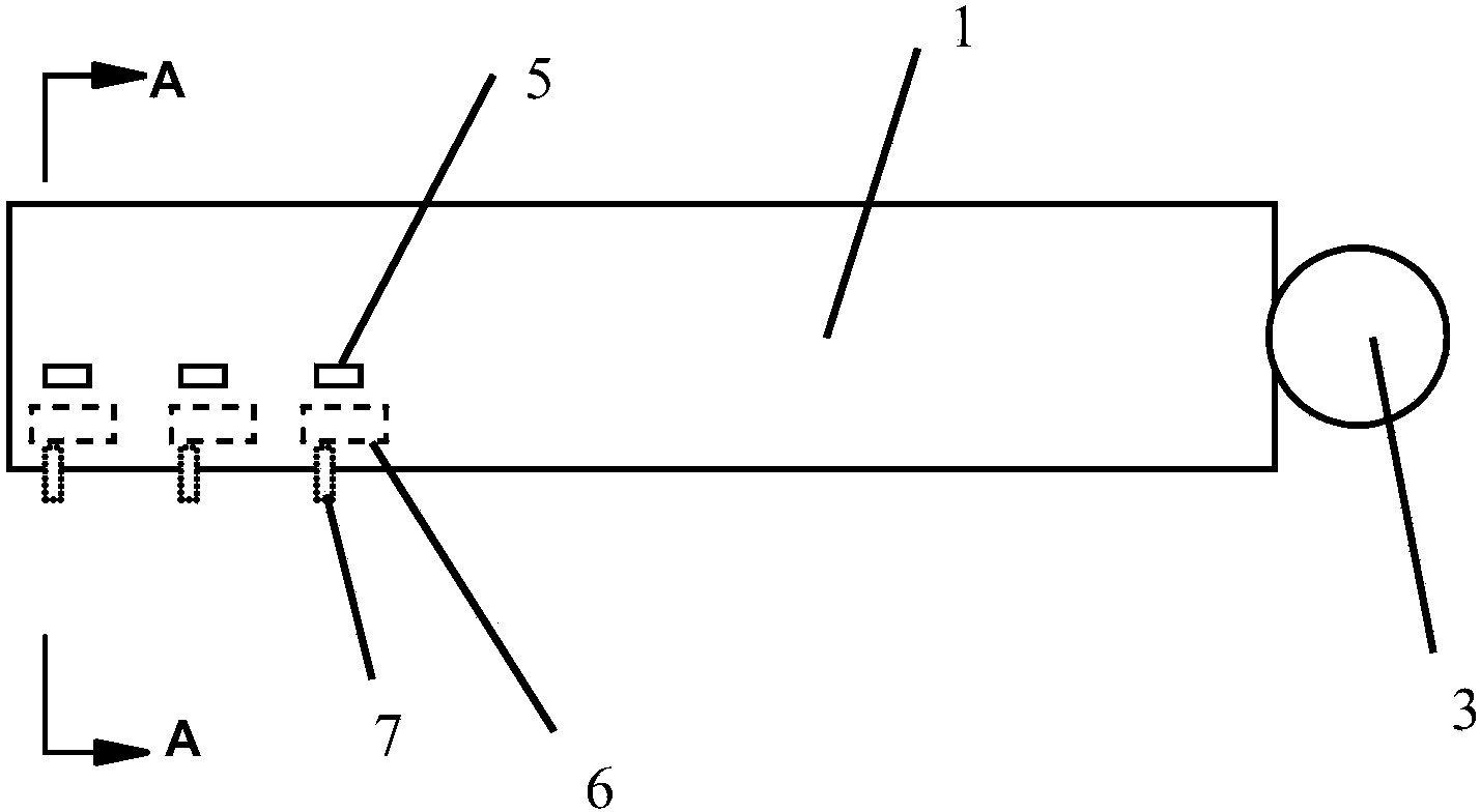
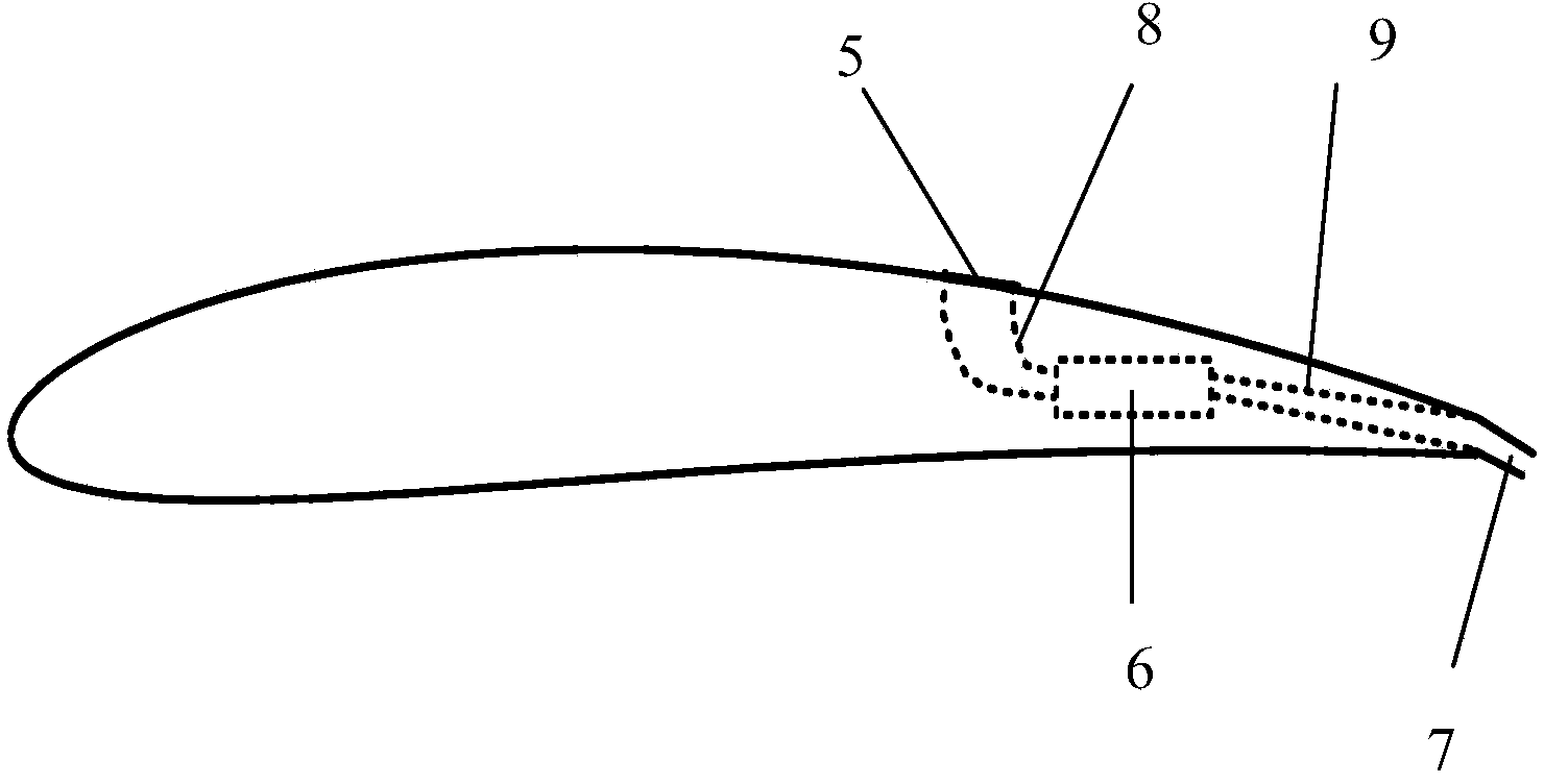
[0018] refer to figure 1 , figure 2 , image 3 , the propeller of the trailing edge jet in the present embodiment is jointly driven by the motor and the jet device. The propeller of the trailing edge jet includes two symmetrical blades 1 , a rotating shaft 3 and a motor 4 , and a plurality of jet devices 2 . The jet device 2 is composed of an air pump 6, a front duct 8, and a rear duct 9. The two ends of the air pump 6 are fixedly connected to one end of the front duct 8 and the rear duct 9 respectively, and the other end of the front duct 8 is connected to the suction port 5 on the upper surface of the blade 1. The other end of the rear conduit 9 is connected to the air outlet 7 on the trailing edge, and the air injection device 2 sucks in the airflow from the air inlet 5 on the upper surface of the blade, and ejects the airflow at a certain angle from the air outlet 7 on the trailing edge after acceleration ...


PUM


Abstract

The invention discloses a propeller with a trailing edge for air jetting. The propeller consists of a plurality of air jetting devices, a rotating shaft, a motor and two symmetrical blades, wherein the motor is located at one end of the rotating shaft; the rotating shaft is connected with an output shaft of the motor through a coupling, and the other end of the rotating shaft is fixedly connected with the propeller; the air jetting devices are embedded in the blades at equal intervals, and are located at positions of 60%-95% spanwise length of the blades; two ends of air pumps are respectively and fixedly connected with one ends of front conduits and one ends back conduits, the other ends of the front conduits are communicated with air suction ports in the upper surfaces of the blades, and the other ends of the back conduits are communicated with air jetting ports in the trailing edge. The air jetting devices suck air currents from the air suction ports in the upper surfaces of the blades, the air currents which are accelerated are jetted out of the air jet ports in the trailing edge at a certain angle, and the air jetting direction of the air jet ports can be regulated within 0-90 degrees according to requirements. Counter-acting force which is formed by jetting air currents of the air jetting devices in a rotating plane pushes the propeller to rotate, a torque born by the rotating shaft of the motor is decreased, and the thrust-weight ratio of a propeller system is increased.

Description

technical field [0001] The invention belongs to the field of aviation propellers, in particular to a low Reynolds number trailing edge jet propeller. Background technique [0002] For stratospheric airships that need to stay in the air for a long time, improving the efficiency of the propeller propulsion system is a key technology. For propellers with conventional layout, the blade diameter has the greatest influence on the aerodynamic efficiency, and when considering the structural performance and reliability performance of the blade, the blade diameter is limited. Therefore, in order to further improve the aerodynamic efficiency of the propeller, it can only be realized by increasing the lift coefficient of the blade profile airfoil and reducing the drag coefficient of the blade profile airfoil. At present, the working condition adaptability of the propeller has been improved through plasma flow control, but due to the high energy consumption of the plasma generator, the ...

Claims


Application Information

Patent Timeline
IPC IPC(8): B64C27/467
Inventor 许建华宋文萍杨旭东余雷
Owner NORTHWESTERN POLYTECHNICAL UNIV
Why Eureka
Try Eureka